Method and apparatus to form a virtual power generation collective from a distributed network of local generation facilities

a technology of local generation facilities and distributed networks, applied in the field of system involving power generation and distribution, can solve the problems of not being able to recoup the cost of installation, being more expensive than the amount refunded by the electricity distributor corporations for supplying power back into the grid, and being unable to meet the practical size of a typical consumer's home or business solar panel installation,

Active Publication Date: 2014-05-08
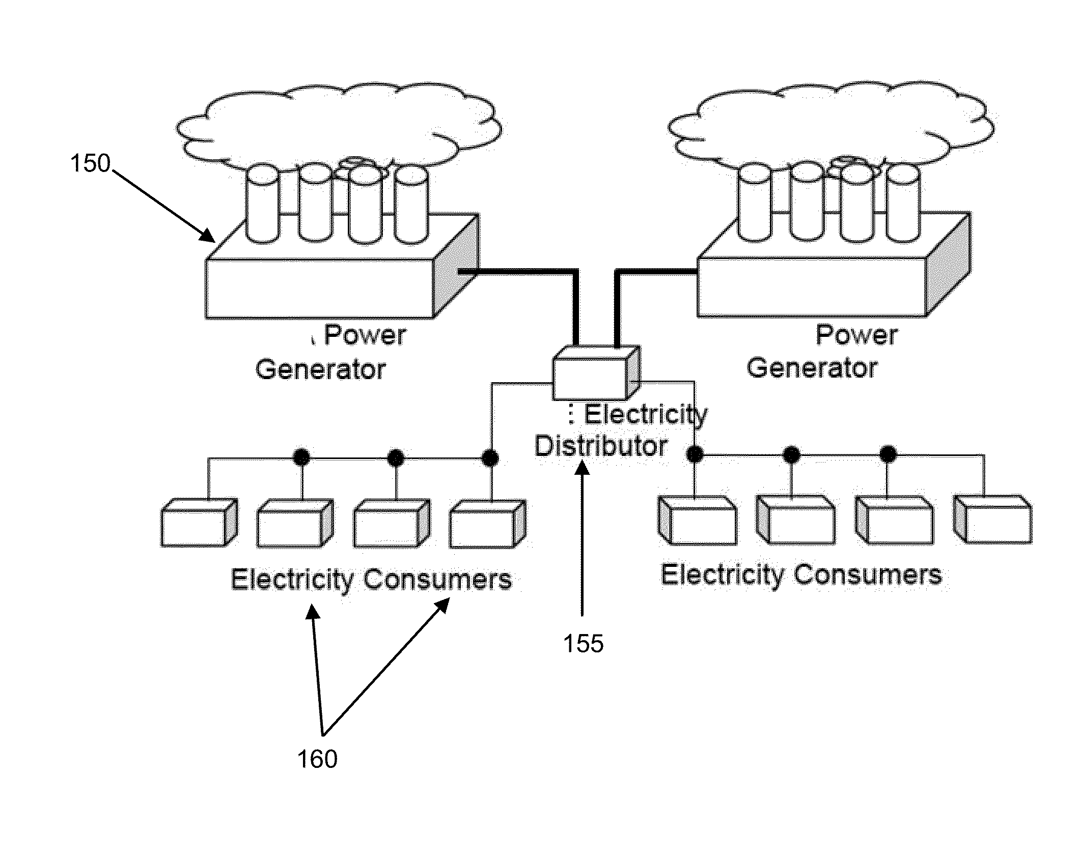
VIRTUAL ELECTRIC INC
View PDF5 Cites 26 Cited by
  • Summary
  • Abstract
  • Description
  • Claims
  • Application Information

AI Technical Summary

Benefits of technology

[0026]In one embodiment, an apparatus for measuring power is presented. The apparatus comprises a meter coupled to a power generation plant at a local facility, wherein the meter comprises: (a) a current sense module operatively coupled to a processor, wherein the processor in conjunction with the current sense module is operable to compute power contributed by the power generation plant; (b) a memory operable to store computed power contribution, and a first set of encryption keys used to communicate securely with a grid provider; and (c) a network interface operable to communicate with the grid provider, wherein a communication between the meter and the grid provider is secured using the first set of encryption keys, and wherein the communication comprises relaying the computed power contributions to the grid provider.

Problems solved by technology

The problem with the present model of power distribution and accounting is that consumer power generation capabilities are in effect competing with corporate generation, and the corporations, in particular, the grid providers, may choose to reward contributions back into the grid at a much reduced rate, substantially lower than the price the electricity supplier would charge consumers drawing from the grid.
This is problematic especially because while the purchase and installation cost of the solar electric panels is less per kwh over the life of the solar panels than the cost of the electricity drawn from the grid, it is typically more expensive than the amount refunded by the electricity distributor corporations for supplying power back into the grid.
These constraints have, in effect, placed an economic limit on the practical size of a home or business solar panel installation for a typical consumer.
In short, if the installation produces more electricity than the typical electrical demand of the home on which it is fitted, it simply cannot recoup the cost of the installation through the money refunded through oversupply going back into the grid.
Unfortunately, this leads to an artificial constraint on the typical home generation installation, wherein the policy of the electricity distributor for the amount of money refunded rather than the installation area or other physical capability of the installation site is the key determinative factor governing the size of the clean solar home generation installation.
Meanwhile, a typical solar installation may cost $0.22 per kwh over the life of the panel.
Under this model, it makes little economic sense for a typical consumer to utilize a solar installation with excess capacity over what the consumer's home or business demands, because any oversupply contributed back into the grid will not be compensated at the same rate as the power consumed.
Similarly, a factory employing wind turbines would face a similar dilemma if the size of the turbine results in excess capacity over what the local facility demands.
However, the problem with sources of electricity being fungible is that it is challenging to distinguish electricity contributed by one provider from another.
Therefore, it is problematic to account for the contributions from the various different types of electricity providers.

Method used


Image

  • Method and apparatus to form a virtual power generation collective from a distributed network of local generation facilities
  • Method and apparatus to form a virtual power generation collective from a distributed network of local generation facilities
  • Method and apparatus to form a virtual power generation collective from a distributed network of local generation facilities

Examples


Embodiment Construction

[0041]Reference will now be made in detail to the various embodiments of the present disclosure, examples of which are illustrated in the accompanying drawings. While described in conjunction with these embodiments, it will be understood that they are not intended to limit the disclosure to these embodiments. On the contrary, the disclosure is intended to cover alternatives, modifications and equivalents, which may be included within the spirit and scope of the disclosure as defined by the appended claims. Furthermore, in the following detailed description of the present disclosure, numerous specific details are set forth in order to provide a thorough understanding of the present disclosure. However, it will be understood that the present disclosure may be practiced without these specific details. In other instances, well-known methods, procedures, components, and circuits have not been described in detail so as not to unnecessarily obscure aspects of the present disclosure.

[0042]S...


PUM


Abstract

A method of accounting for electrical power contribution and consumption is presented. The method comprises receiving information, from a plurality of facilities, wherein the plurality of facilities is operable to generate and/or consume electricity, and wherein the data comprises information concerning electricity contributions to a power grid, and/or consumptions from the grid by the plurality of facilities. The method further comprises applying a robust system of cryptographic processes to said information concerning electricity contributions, and attest to the authenticity of the information, as well as to the correct attribution of the facility claimed. Finally, the method comprises tracking and accounting electricity contributions and/or consumptions from each of the plurality of facilities using decrypted and verified information in a manner that allows contributions to be independently verified through audits. The method can also comprise compensating each of the facilities based on the respective electricity contribution and/or consumption of each facility.

Description

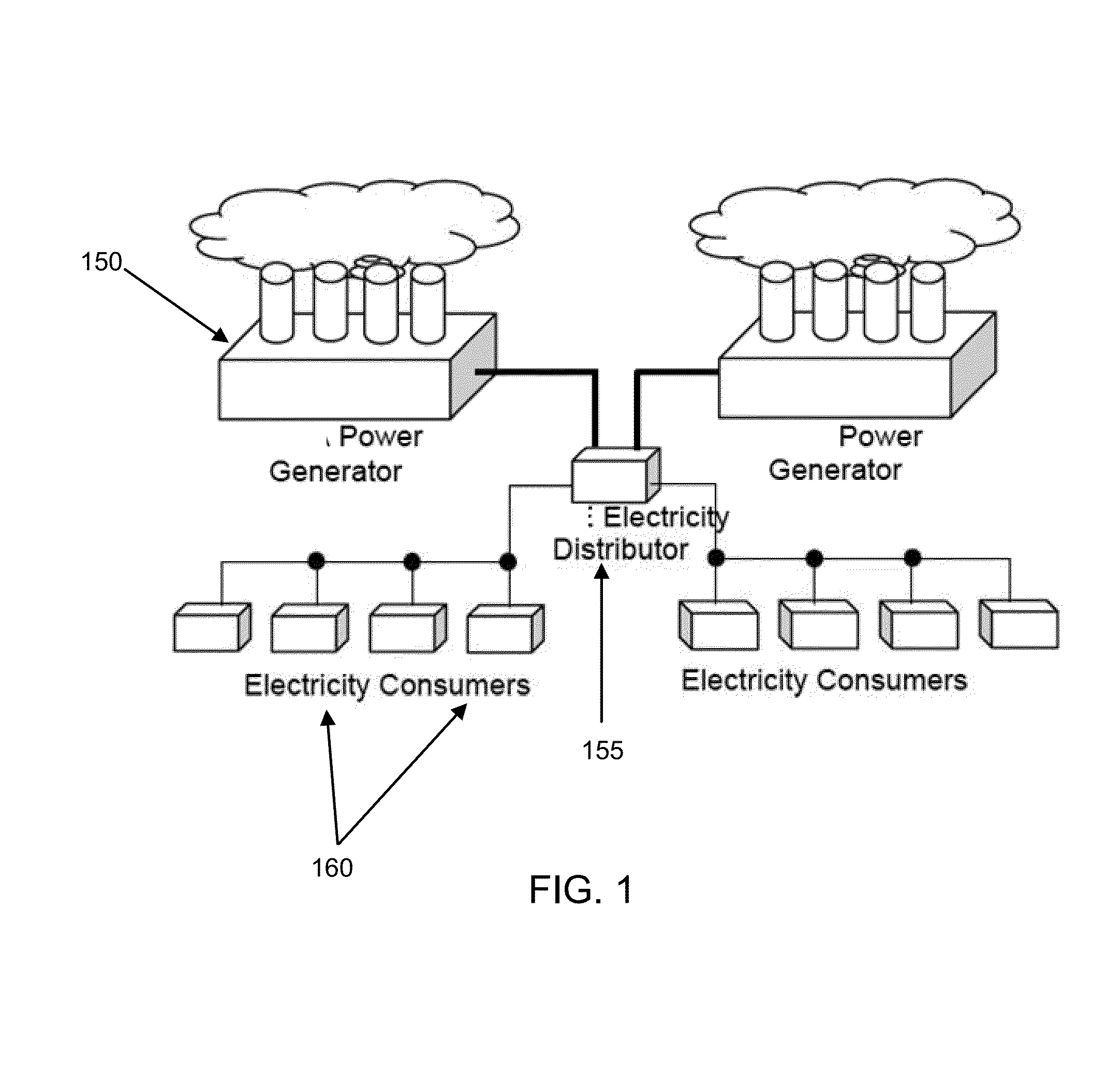
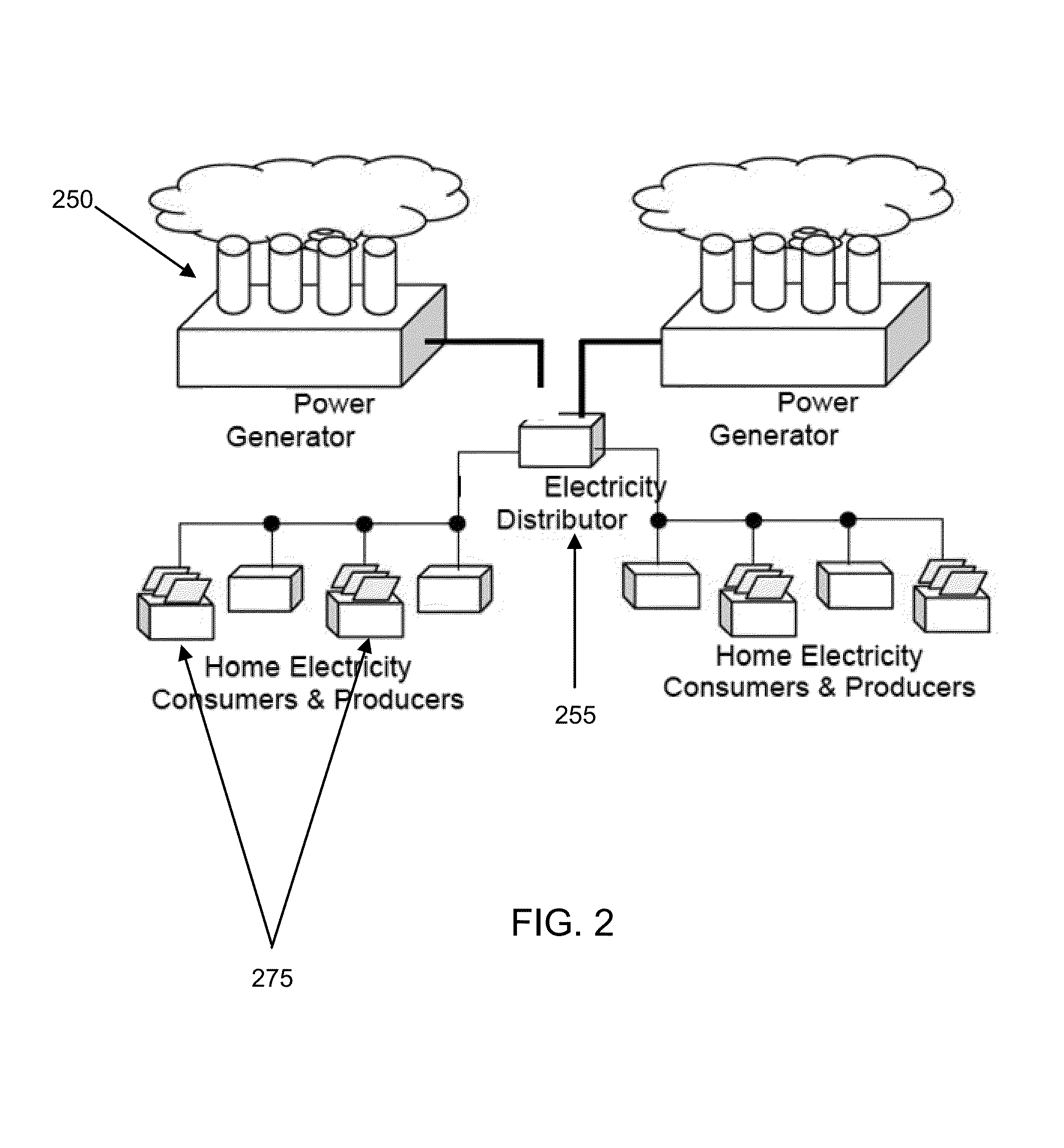
CROSS-REFERENCE TO RELATED APPLICATIONS[0001]This application claims priority from U.S. Provisional Patent Application Ser. No. 61 / 624,190, “METHOD AND APPARATUS TO FORM A VIRTUAL POWER GENERATION COLLECTIVE FROM A DISTRIBUTED NETWORK OF LOCAL GENERATION FACILITIES,” Attorney Docket WYAT-P0001.PRO, David Wyatt, filed Apr. 13, 2012, the entire disclosure of which is incorporated herein by reference.FIELD OF THE INVENTION[0002]Embodiments according to the present invention generally relate to systems involving power generation and distribution and more specifically to methods for measuring and accounting for generated and distributed power.BACKGROUND OF THE INVENTION[0003]Historically, electrical power has been delivered from a power generation facility, for example, Northern California Power Agency (“NCPA”), to an end-consumer at a home or business facility through an electricity distributor, for example, Pacific, Gas and Electricity Company (“PG&E”). The power can usually be provisi...

Claims


Application Information

Patent Timeline
Patent Type & Authority Applications(United States)
IPC IPC(8): H02J3/00
CPCH02J3/008Y02B10/30G06Q30/04G06Q50/06G01D4/002Y02B90/20Y04S20/30Y04S50/12
Inventor WYATT, DAVID
Owner VIRTUAL ELECTRIC INC
Why Eureka
Try Eureka