Capacitor

a capacitor and self-inductance technology, applied in the field of capacitors, can solve the problems of difficulty in assembling the parts into capacitors, difficulty in holding parts, and insufficient self-inductance, and achieve the effect of reducing cost and lowering self-inductan

Active Publication Date: 2014-05-08
SOSHIN ELECTRIC
View PDF0 Cites 38 Cited by
  • Summary
  • Abstract
  • Description
  • Claims
  • Application Information

AI Technical Summary

Benefits of technology

[0017]The capacitor according to the present invention does not require a dedicated connecting structure to be prepared, is able to deal flexibly with specification changes, is of a reduced cost, and has its self-inductance lowered.
[0018]Usually, when a current greater than an allowable current flows through a capacitor, the temperature of the capacitor rises with time beyond the allowable temperature for the capacitor until eventually the capacitor may possibly produce smoke and catch fire. However, since the capacitor has the cooling member, the temperature of the capacitor does not go beyond the allowable temperature therefor even when a current greater than an allowable current flows through the capacitor. Therefore, the capacitor is prevented from suffering the above drawbacks.

Problems solved by technology

However, since the illustrated connecting structures are primarily of an insulated design, not enough consideration is given to the connecting length for folded electrodes and hence the self-inductance is not sufficiently lowered.
However, as shown in FIG. 2(e) of Japanese Patent No. 3357314, since the connecting structure is of an integral casing structure, difficulty arises in assembling the parts into a capacitor.
In addition, it is difficult to hold the parts when the connecting and extension plates are connected, and also to assemble the parts.
The dedicated connecting structure is unable to deal with specification changes and is liable to cause an increase in cost.
Although the capacitor disclosed in Japanese Patent No. 3357314 is said to have its self-inductance reduced to about ¼ of conventional capacitors, the stated reduction in the self-inductance is not sufficient.

Method used


Image

  • Capacitor
  • Capacitor
  • Capacitor

Examples


##ventive examples 1 through 8

Inventive Examples 1 Through 8

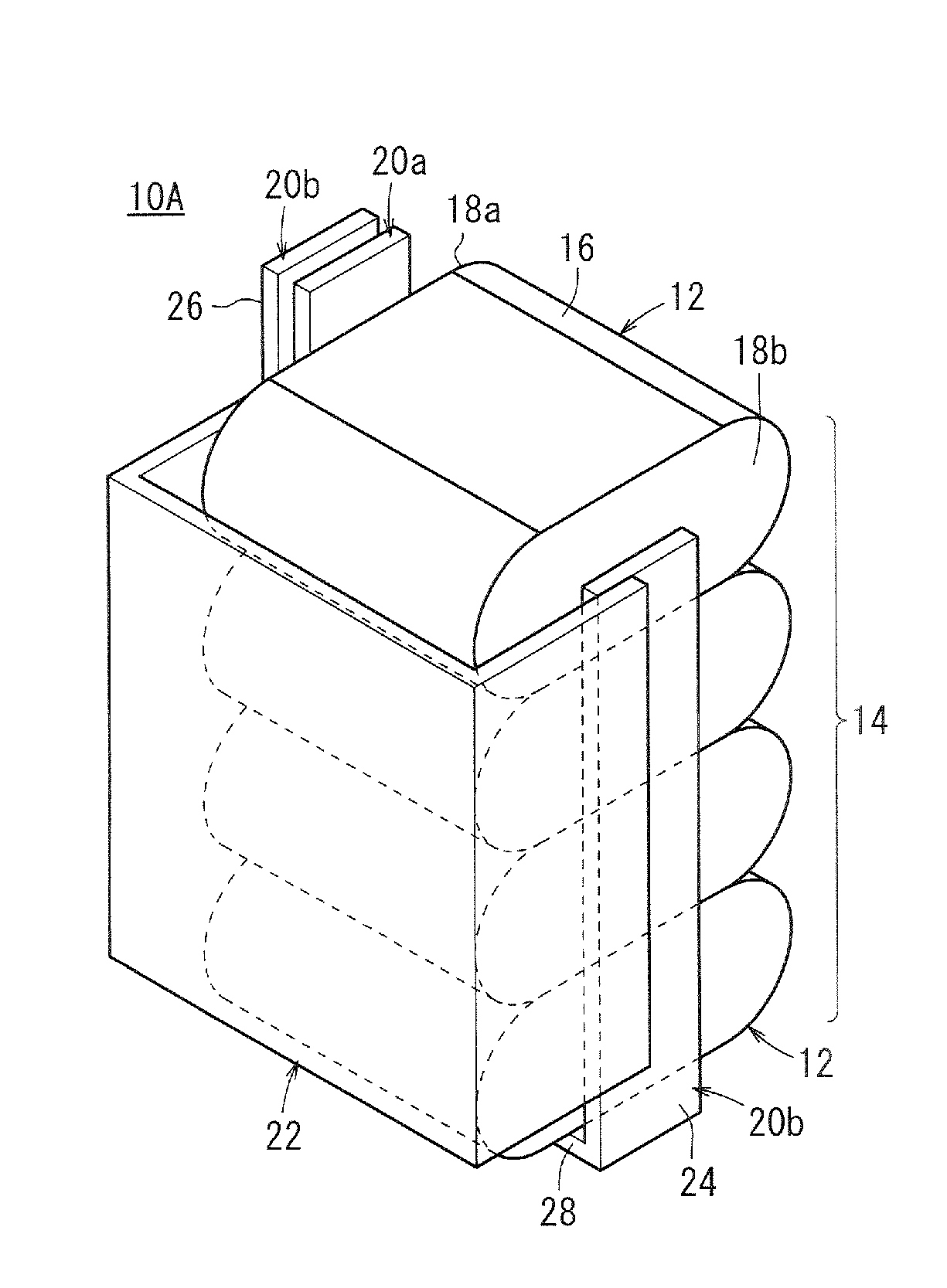
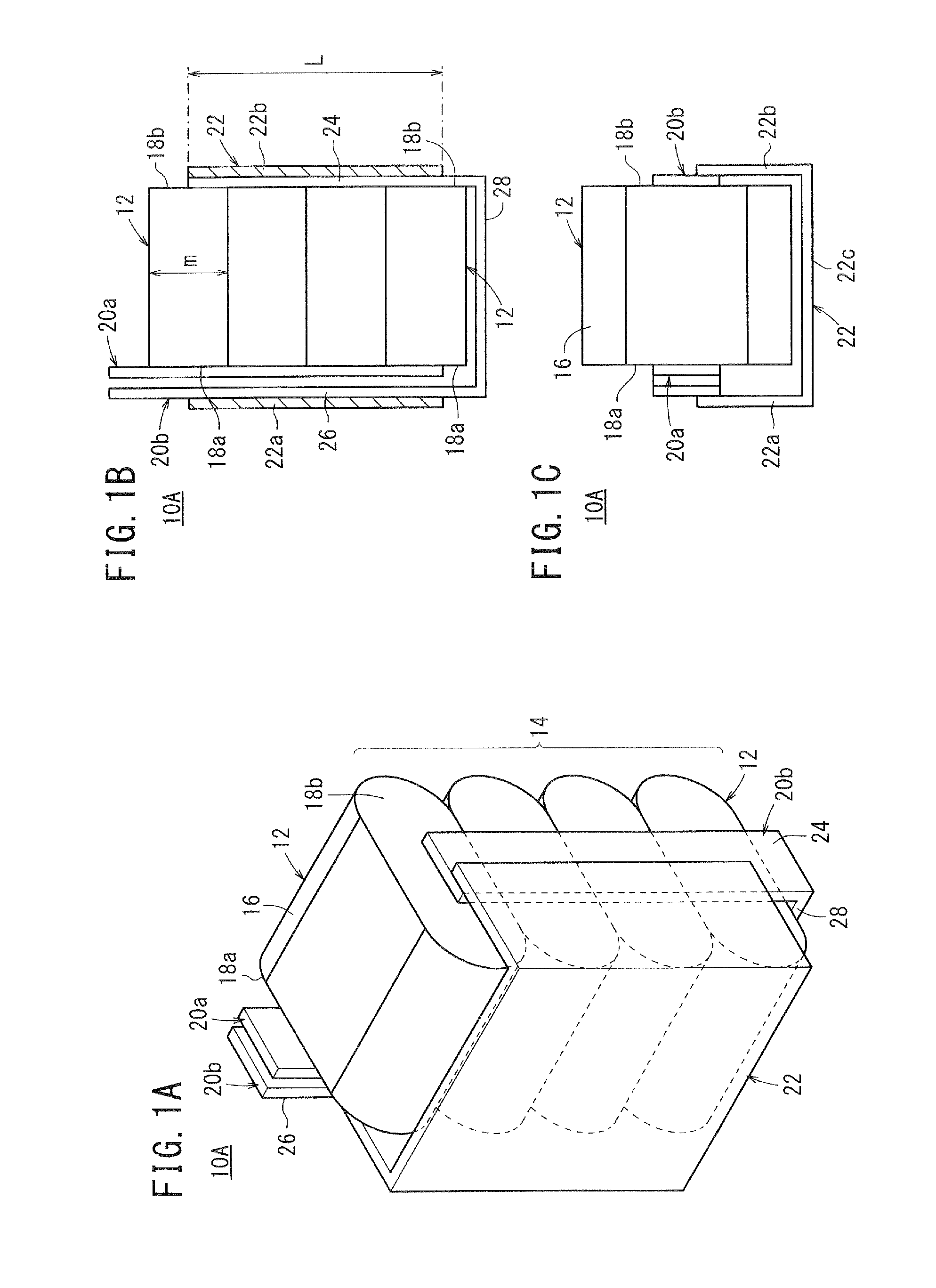
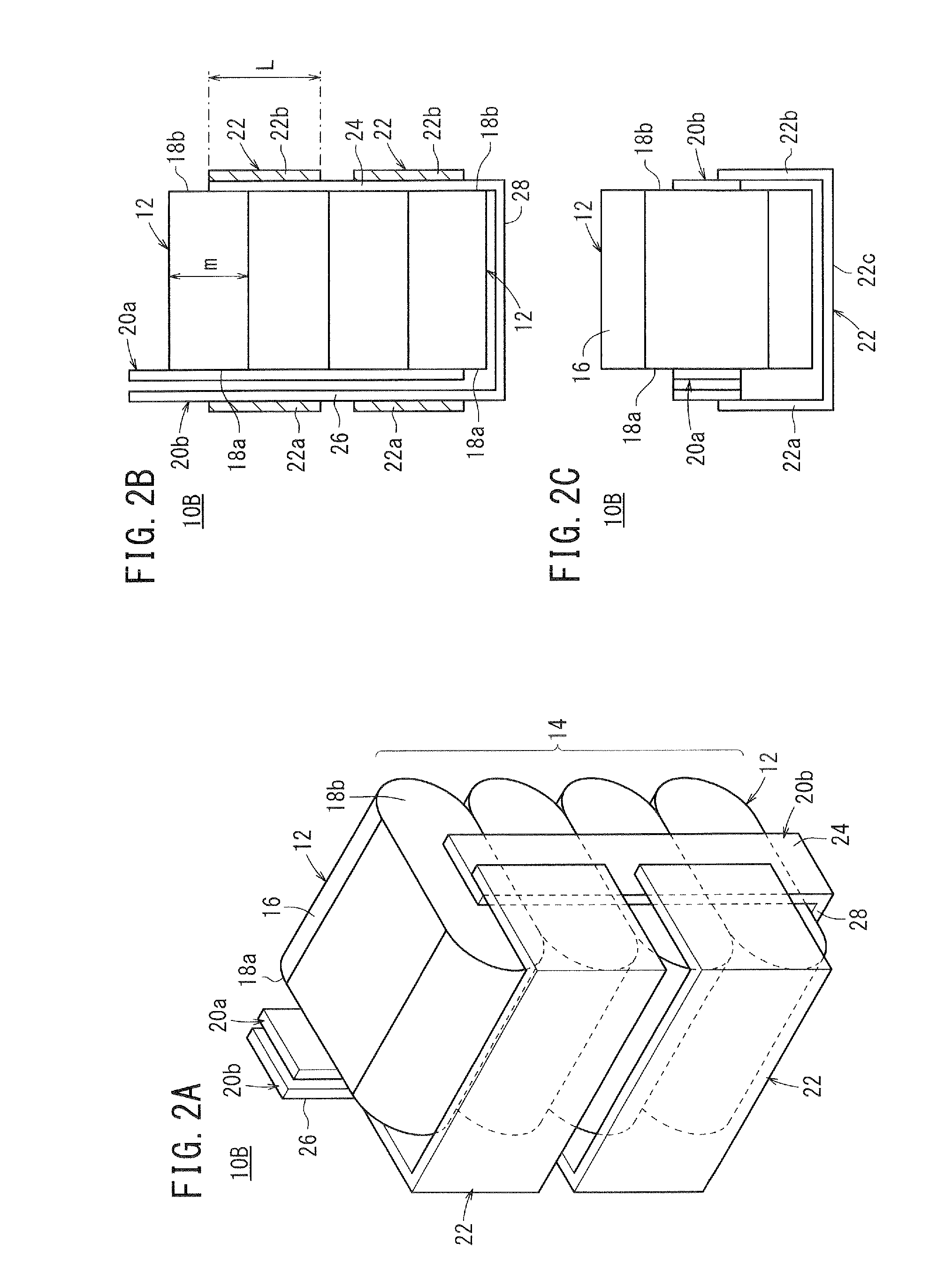
[0078]The capacitor according to Inventive Example 1 is identical in structure to the first capacitor 10A shown in FIGS. 1A through 1C. The capacitor according to Inventive Example 2 is identical in structure to the second capacitor 10B shown in FIGS. 2A through 2C. The capacitor according to Inventive Example 3 is identical in structure to the third capacitor 10C shown in FIGS. 3A through 3C. The capacitor according to Inventive Example 4 is identical in structure to the fourth capacitor 10D shown in FIGS. 4A through 4C. The capacitor according to Inventive Example 5 is identical in structure to the fifth capacitor 10E shown in FIGS. 5A through 5C. The capacitor according to Inventive Example 6 is identical in structure to the sixth capacitor 10F shown in FIGS. 6A through 6C.

[0079]The capacitor according to Inventive Example 7 is identical in structure to the ninth capacitor 10I shown in FIG. 9. The capacitor according to Inventive Example 8 is identic...


PUM


Abstract

This capacitor has: a single capacitor block provided with a plurality of capacitor elements electrically connected in parallel, each of said capacitor elements having a terminal part on each end; a first electrode plate that electrically connects the first terminal parts of the capacitor elements; a second electrode plate that electrically connects the second terminal parts of the capacitor elements and continues on to the side where the first terminal parts are; and at least one bypass electrode plate that electrically bypasses the second electrode plate.

Description

TECHNICAL FIELD[0001]The present invention relates to a capacitor employing a capacitor block made up of a plurality of capacitor elements which are electrically connected parallel to each other.BACKGROUND ART[0002]Generally, a capacitor having a large capacitance in excess of 100 μF employs a capacitor block that is fabricated by preparing a plurality of capacitor elements each having a capacitance smaller than 100 μF or of about 100 μF in order to provide a required electrostatic capacitance and connecting the capacitor elements parallel to each other with connectors such as flat-stranded copper wires or the like. Some capacitors have a plurality of such capacitor blocks connected parallel to each other.[0003]When such a capacitor is used as a smoothing capacitor in an electric power converter such as an inverter or the like, a ripple current having a carrier frequency or the like from the inverter flows through the capacitor. At this time, the capacitor elements and the connector...

Claims


Application Information

Patent Timeline
Patent Type & Authority Applications(United States)
IPC IPC(8): H01G4/38
CPCH01G4/385H01G4/38H01G2/08H01G4/232H01G4/248H01G4/228
Inventor YODA, TAKEHARUTATEYAMA, KENICHIYANAGIHASHI, KIYOKAZUKATO, YOSHIKUNI
Owner SOSHIN ELECTRIC
Why Eureka
Try Eureka