Protective device and protective module

a technology of protective device and protective module, which is applied in the direction of emergency protective circuit arrangement, circuit arrangement, electrical equipment, etc., can solve the problems of arcing effect, circuit breakage, and fuse cannot provide protection function, so as to prevent a broken circuit, improve insulation impedance, and reduce the number of conductive objects

Active Publication Date: 2014-05-15
CYNTEC
View PDF3 Cites 10 Cited by
  • Summary
  • Abstract
  • Description
  • Claims
  • Application Information

AI Technical Summary

Benefits of technology

[0015]In an embodiment of the present invention, since the protective device includes the arc extinguishing structure composed of the inorganic particles or made of polysiloxanes, the arc extinguishing effect is improved to induce less number of conductive objects, and moreover the conductive objects accumulated in the gap are isolated to prevent a broken circuit from being electrically conducted by the conductive objects. Moreover, in an embodiment of the present invention, the arc extinguishing structure disposed on the inner surface of the outer cover also can prevent electrically conduction paths

Problems solved by technology

When a transient current exceeds a predetermined value, the heat energy caused by the transient overcurrent will melt the safety fuse, and thus the circuit is broken.
In the breaking capacity test, a high power is applied, and the safety fuse of the overcurrent and overvoltage protective device will be transitorily melted, thereby

Method used


Image

  • Protective device and protective module
  • Protective device and protective module
  • Protective device and protective module

Examples


Embodiment Construction

[0055]The present invention will now be described more specifically with reference to the following embodiments. It is to be noted that the following descriptions of preferred embodiments of this invention are presented herein for purpose of illustration and description only. It is not intended to be exhaustive or to be limited to the precise form disclosed.

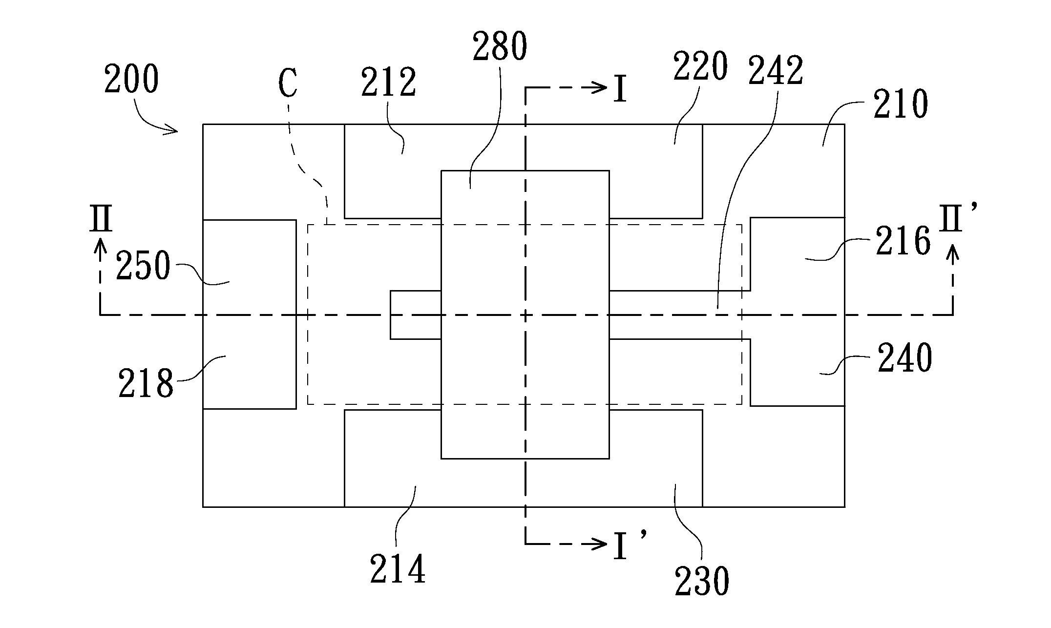
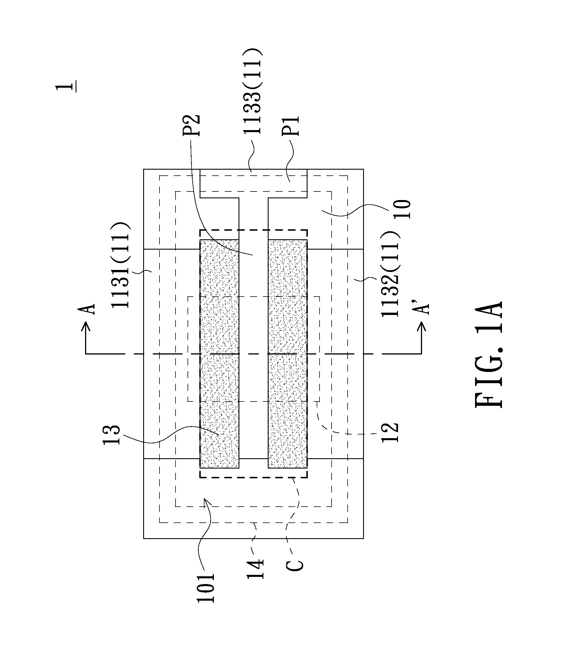
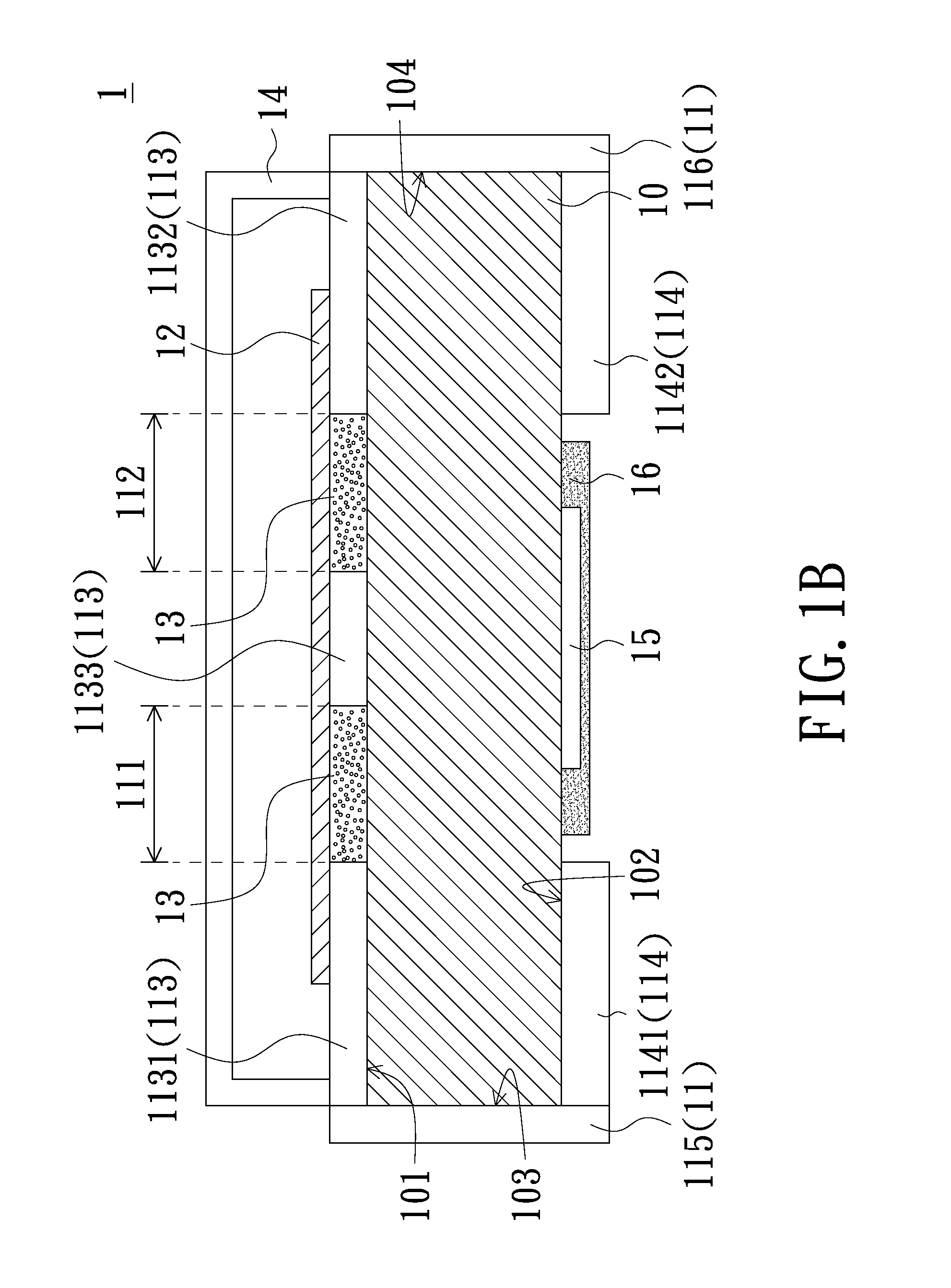
[0056]FIG. 1A is a schematic perspective top view of a protective device according to an embodiment of the present invention, and FIG. 1B is a schematic cross-sectional view taken along line A-A′ in FIG. 1A. Referring to FIGS. 1A and 1B, the protective device 1 of the present embodiment is, for example, a protective device with overcurrent and overvoltage protective function (OCP, OVP). The protective device 1 includes a substrate 10, an electrode layer 11, a metal structure 12, an arc extinguishing structure 13 and an outer cover 14. The electrode layer 11 is disposed on substrate 10, and the electrode layer 11 includes gaps 111...


PUM


Abstract

A protective device includes a substrate, an electrode layer, a metal structure, an outer cover and an arc extinguishing structure. The electrode layer is disposed on the substrate. The electrode layer includes at least one gap. The metal structure is disposed on the electrode layer and located above the gap, and the metal structure has a melting temperature lower than a melting temperature of the electrode layer. The outer cover is disposed on the substrate and covers the metal structure and a portion of the electrode layer. The arc extinguishing structure is disposed between the outer cover and the substrate. A protective module is further provided.

Description

CROSS-REFERENCE TO RELATED APPLICATIONS[0001]The present application is a continuation-in-part application claiming benefit of US patent application bearing a Ser. No. 13 / 894,160 filed May 14, 2013, which is a divisional application claiming benefit of U.S. patent application Ser. No. 12 / 875,752 filed Sep. 3, 2010, now U.S. Pat. No. 8,472,158 issued Jun. 25, 2013, claiming benefit of Taiwanese Patent Application No. 98129872 filed Sep. 4, 2009, 98129874 filed Sep. 4, 2009, and 99115506 filed May 14, 2010, respectively. The entirety of each of the above-mentioned patent application is hereby incorporated by reference herein and made a part of this specification. The present application is also based upon and claims the benefit of priority from the prior Taiwanese Patent Application No. 102125568, filed Jul. 17, 2013, the entire contents of which are incorporated herein by reference.FIELD OF THE INVENTION[0002]The present invention relates to a protective device, and more particularly...

Claims


Application Information

Patent Timeline
IPC IPC(8): H01H85/041
CPCH01H85/0411H01H69/022H01H85/0047H01H85/046H01H85/048H01H85/11H01H85/18H01H2085/466H01H85/0065
Inventor WANG, CHUNG-HSIUNGLIN, HUNG-MINGCHIANG, LANG-YILUO, WEN-SHIANGCHEN, KUO-SHUCHUNG, HAN-YANGHSU, HUI-WENSU, PO-WEICHEN, HONG-MING
Owner CYNTEC
Why Eureka
Try Eureka