Mechanical actuator with a hydraulic damper device

a technology of damper device and mechanical actuator, which is applied in mechanical apparatus, transportation and packaging, and gearing. it can solve the problems of wear or lack of reliability, inconvenient emergency operation of actuators, and difficult organization

Active Publication Date: 2014-05-22
SAFRAN LANDING SYSTEMS
View PDF21 Cites 16 Cited by
  • Summary
  • Abstract
  • Description
  • Claims
  • Application Information

AI Technical Summary

Benefits of technology

[0013]This mode of operation of the actuator may be used when the load coupled to the actuator (e.g. aircraft landing gear) causes the rod to move under drive from the load, e.g. under the effect of gravity. The damping as organized in this way serves to regulate the travel speed of the load. The motor of the actuator is then not used for controlling said speed, thereby sparing the motor. This naturally assumes that the connection between the nut and the screw is reversible.
[0015]Thus, e.g. in the event of a failure of the motor causing the screw to block, it is possible to separate the rod from the nut, and thus allow the rod to slide freely under the effect of the load. Before being separated, care should naturally be taken to operate the solenoid valve to activate hydraulic damping as described above so that the travel speed of the load can be controlled while the rod is returning under the action of the load.
[0017]It should be observed that in the actuator of the invention, the fluid is used only for damping or braking movements of the rod, and not for driving said movements, unlike actuators having an incorporated pump, or double-acting actuators such as that of document FR 2 859 770. Thus, advantage is taken of hydraulic damping only when it is necessary. It should also be observed that the actuator is not filled with oil like the actuator described in document FR 2 946 618, thereby leading to significant lightening.
[0019]According to a particularly advantageous aspect of the invention, a method is provided of monitoring an actuator of the invention, the method consisting in leaving the rod to move freely solely under the action of a load coupled to the rod, and in verifying at least one operating parameter of the landing gear associated with the hydraulic damping. In particular, the length of time taken by the rod to move under the effect of the load against the hydraulic damping as organized in this way is verified, thereby making it possible to verify proper operation thereof.

Problems solved by technology

Nevertheless, such an actuator is not suitable for emergency operation in which the rod is driven by the load to which it is coupled, unless the pump is reversible and is capable of being released.
Nevertheless, the first type of resistance is essentially independent of the travel speed of the rod, while the second type of resistance is rather difficult to organize and in general is a function of the travel speed of the rod, and that might be found to be insufficient in certain applications.
In addition, such damping leads to numerous problems in service, such as wear or lack of reliability.

Method used


Image

  • Mechanical actuator with a hydraulic damper device
  • Mechanical actuator with a hydraulic damper device
  • Mechanical actuator with a hydraulic damper device

Examples


Embodiment Construction

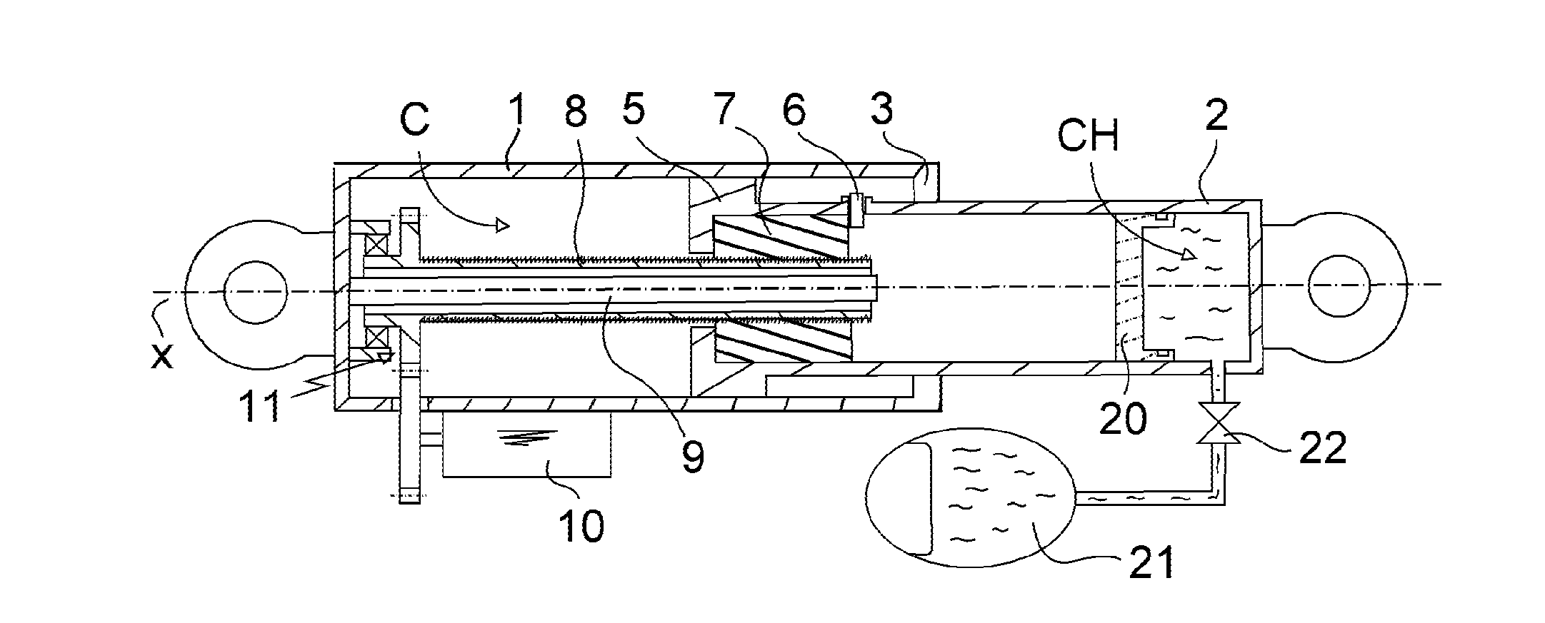
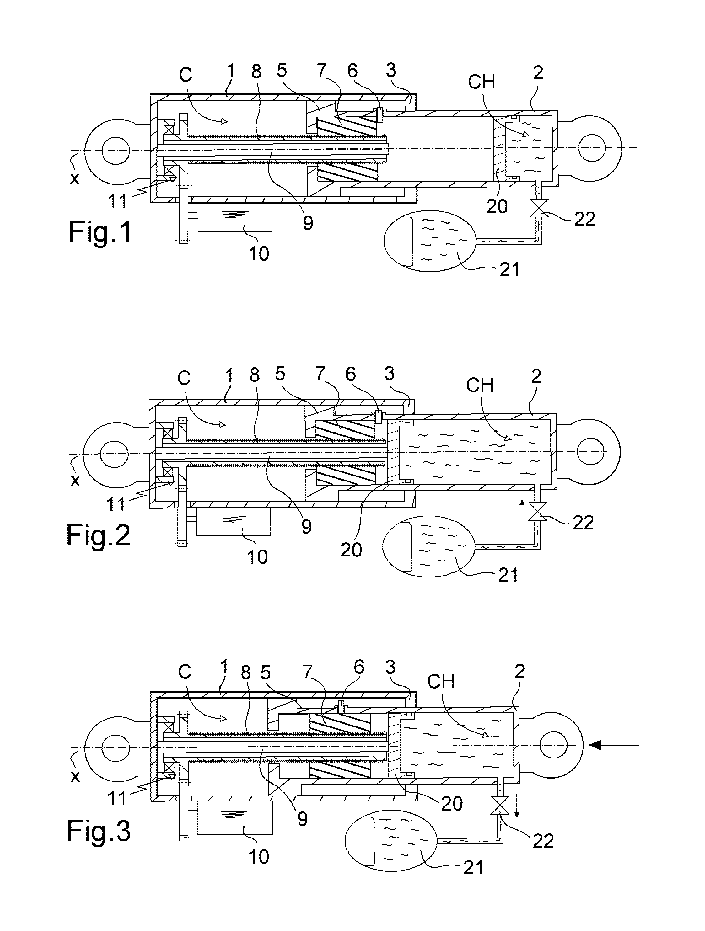
[0026]With reference to FIG. 1, the actuator of the invention comprises a cylinder 1 defining a cylindrical cavity C extending along a longitudinal axis X. The actuator has a hollow rod 2 that extends axially inside the cavity C in order to pass through an end wall 3 forming a bearing that closes the cavity C at one of its ends. The rod 2 is terminated inside of the cavity C by an open end forming a bearing 5 slidable in the cavity C.

[0027]Internally, the bearing 5 defines a housing that receives a nut 7 mounted in said housing, such that the rod 2 and the nut 7 are held together by a locking device 6 (a finger in this example). A command tending to counteract the locking device serves to separate the rod 2 from the nut 7 so that the rod 2 can slide freely, independently of the nut 7.

[0028]A screw 8 mounted to rotate in the cylinder 1 extends axially in the rod 2 to co-operate with the nut 7 by means of a helical type connection.

[0029]In this example, the screw 8 is driven in rotati...


PUM


Abstract

The invention relates to an actuator comprising a cylinder (1) in which a rod (2) is mounted to slide, the actuator having a screw (8) extending inside the rod to co-operate with a nut (7) secured to the rod, the screw being driven in rotation by a motor (10), the actuator being characterized in that a hydraulic chamber (CH) filled with hydraulic fluid is arranged inside the actuator by means of a floating piston (20) sliding in sealed manner against the rod inside of the actuator, the hydraulic chamber being in fluid flow communication with an accumulator (21) via a solenoid valve (22) that is controllable between a closed state in which the chamber is isolated from the accumulator, and a fluid-passing state in which the hydraulic chamber and the accumulator are in communication, calibrated resistance being exerted against the passage of fluid from the chamber towards the accumulator.

Description

[0001]The invention relates to a mechanical actuator having a controlled damper device.[0002]The present invention relates to an electromechanically operated actuator with hydraulic damping that is particularly advantageous for operating the landing gear of an aircraft between a deployed position and a retracted position.BACKGROUND OF THE INVENTION[0003]Telescopic type hydraulic actuators are known that comprise a cylinder defining a spherical cavity and a rod that extends through one end of the cavity, being secured to a piston that is mounted to slide axially inside the cavity so as to define two hydraulic chambers therein.[0004]During a movement of the rod, it is known to organize throttling on the outlet from the chamber from which fluid is expelled in order to perform hydraulic damping. Such throttling generates resistance that is proportional to the square of the travel speed of the rod.[0005]Electrohydraulic actuators are also known that have an electric pump arranged to move...

Claims


Application Information

Patent Timeline
Patent Type & Authority Applications(United States)
IPC IPC(8): B60G15/12F16H25/20
CPCB64C25/18B64C25/22F16H25/2021Y10T74/18648B60G15/12F16H25/20
Inventor LEGLIZE, LUDOVIC
Owner SAFRAN LANDING SYSTEMS
Why Eureka
Try Eureka