Vehicle wheel lathe fixture

a technology of lathes and wheels, applied in the field of lathes, can solve the problems of low positioning accuracy, failure to position, and the limitation of the compatibility range of modes that is generally not more than 2-3 mm, and achieve the effects of wide compatibility range, reliable work, and stable operation

Inactive Publication Date: 2017-11-02
CITIC DICASTAL
View PDF5 Cites 14 Cited by
  • Summary
  • Abstract
  • Description
  • Claims
  • Application Information

AI Technical Summary

Benefits of technology

[0011]The present invention has the characteristics of reliable work, stable operation ...

Problems solved by technology

The conventional lathe fixture performs radial positioning by the floating disc, leading to low positioning accuracy, and may fail to position normally due to the deformation of roundness of the vehicle wheel.
In recent years, various improvements of p...

Method used


Image

  • Vehicle wheel lathe fixture
  • Vehicle wheel lathe fixture
  • Vehicle wheel lathe fixture

Examples


Embodiment Construction

[0015]The details and operation of the specific devices provided according to the present invention will be now described in details with reference to the accompanying drawings.

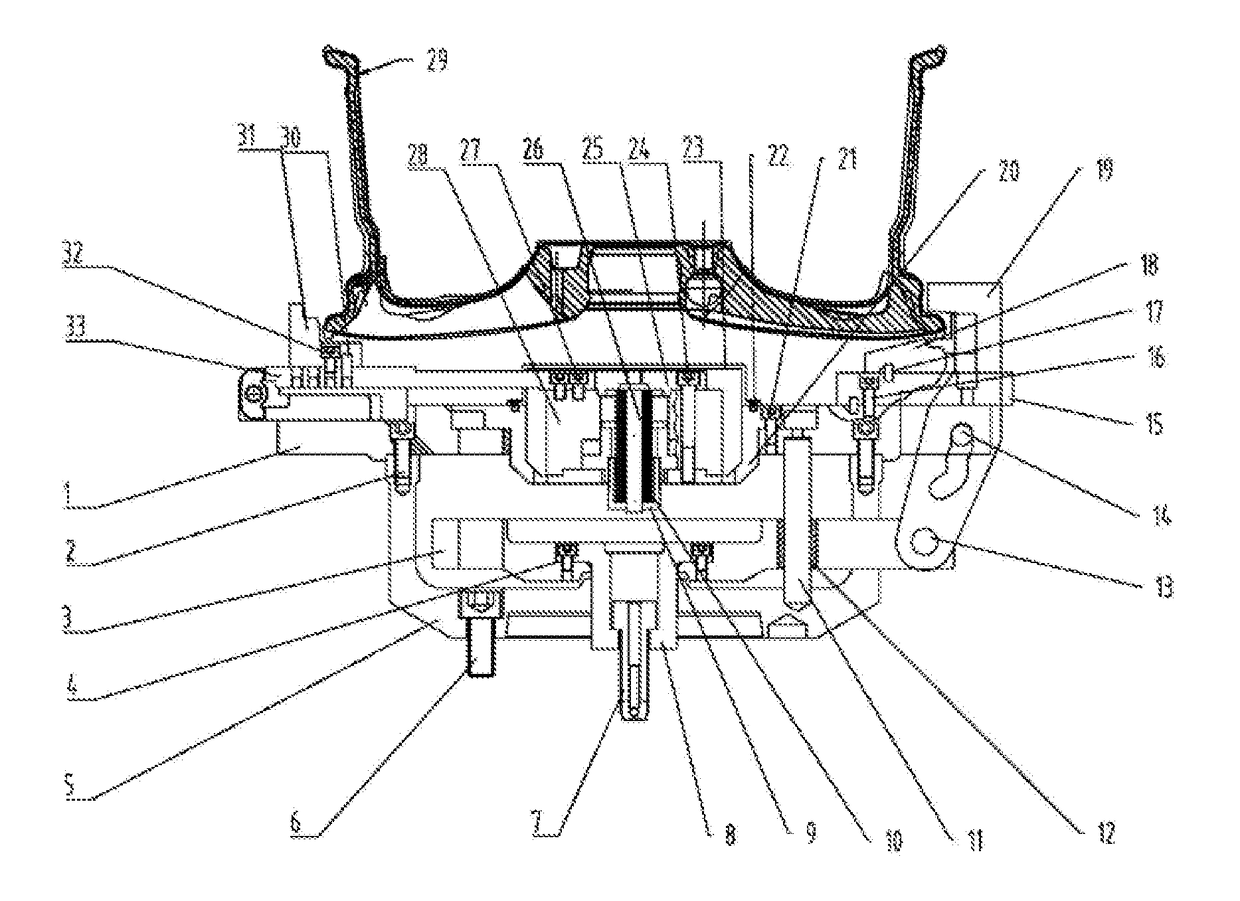
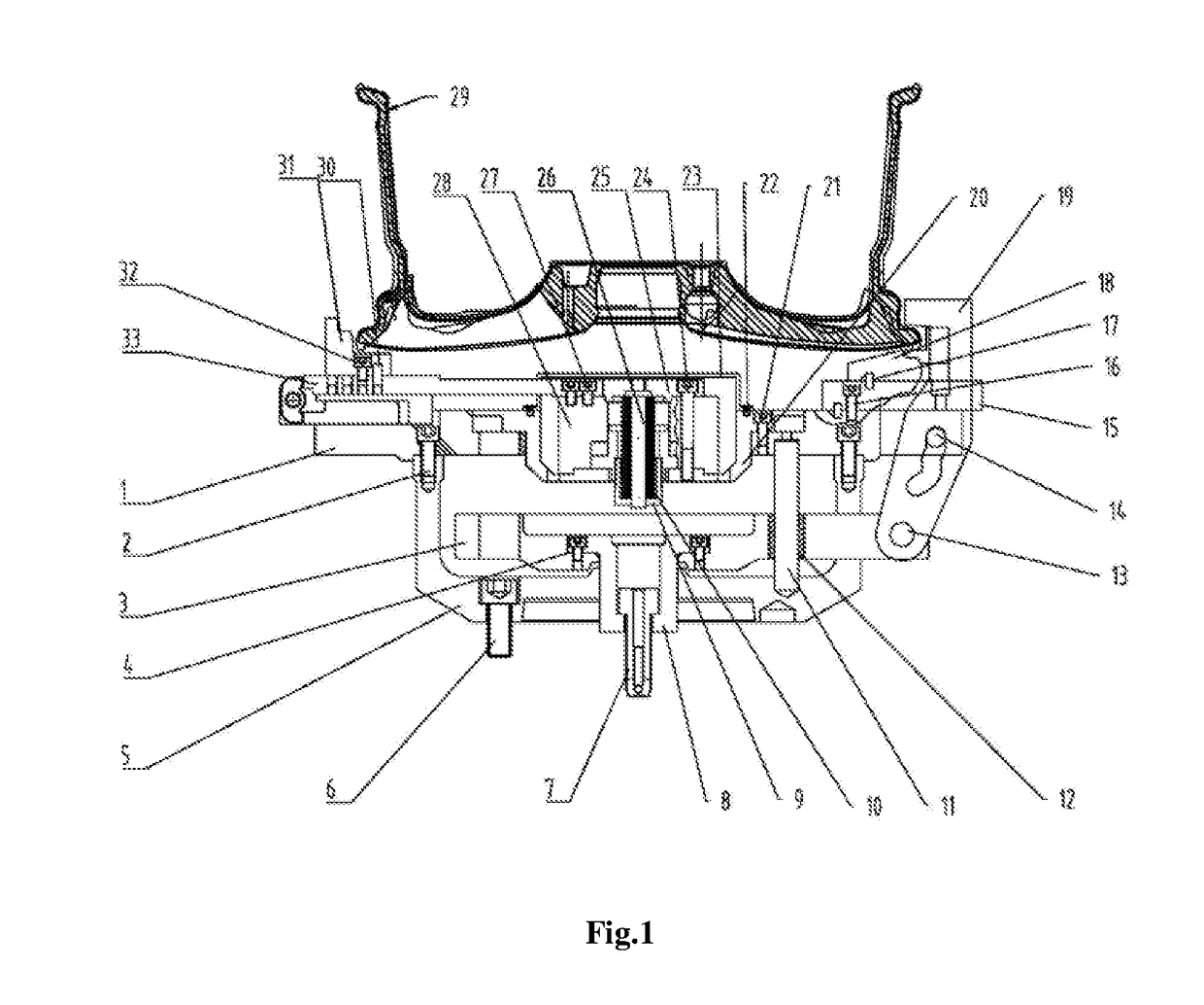
[0016]A vehicle wheel lathe fixture comprises an upper cover 1, a coupling base 5, a guide pin 11, a floating disc 3, a driving seat 8, a sliding sleeve 12, a finger-shaped press jaw 19, a rotating shaft 13, a sliding shaft 14, an end-face positioning block base 15, an end-face positioning block 18, a radial positioning block 31, a radial pull rod 33, a hydraulic power chuck 28, a disc spring sleeve 9, a disc spring 10, a disc spring positioning column 26, a press cover 25, a hydraulic power chuck mounting base 20, and a dust cover 23. The coupling base 5 and the upper cover 1 are installed together via a bolt A 2 to form a housing of the entire fixture, and to provide a basis for installation of individual parts, the guide pin 11 is arranged between the upper cover 1 and the coupling base, the floating disc ...


PUM

PropertyMeasurementUnit
Compatibilityaaaaaaaaaa

Abstract

A vehicle wheel lathe fixture, including an upper cover, a coupling base, a floating disc, a driving seat, a sliding sleeve, a finger-shaped press jaw, a rotating shaft, a sliding shaft, an end-face positioning block base, an end-face positioning block, a positioning pin, a radial positioning block, a radial pull rod, a hydraulic power chuck, a disc spring sleeve, a disc spring, a disc spring positioning column, a press cover, a hydraulic power chuck mounting base and a dust cover. Embodiments of the invention have the characteristics of reliable work, stable operation and wide compatibility range, and is applicable to vehicle wheel mechanical processing lathes.

Description

TECHNICAL FIELD[0001]The present invention relates to a lathe fixture, and in particular to a vehicle wheel lathe fixture.BACKGROUND ART[0002]There is a need for a vehicle wheel to be fixed on a lathe by a dedicated lathe fixture before turning the vehicle wheel.[0003]The conventional lathe fixture performs radial positioning by the floating disc, leading to low positioning accuracy, and may fail to position normally due to the deformation of roundness of the vehicle wheel. In recent years, various improvements of positioning mode have been developed in the vehicle wheel processing industry, for example, floating cone positioning mode, slider positioning mode, etc., however, these modes have the limitation of compatibility range that is generally not more than 2-3 mm.[0004]In terms of clamping mode, the conventional fixture allows the clamping operation of the same type of wheel blanks alone. In the case of changing the wheel, the fixture should be changed as well.SUMMARY OF THE INV...

Claims


Application Information

Patent Timeline
IPC IPC(8): B23B31/30B60B30/06
CPCB23B31/302B60B2310/231B23B2270/025B23B2215/08B23B2231/28B60B30/06B23Q3/12B23B31/16275B23B31/185B23B31/30
Inventor GUO, JIANDONG
Owner CITIC DICASTAL
Why Eureka
Try Eureka