Instrument holder for surgical instrument

a surgical instrument and instrument holder technology, applied in the field of surgical instrument instrument holder, can solve the problems of difficult cleaning of surgical instruments, soiling of instruments and instruments, etc., and achieve the effect of rapid cleaning

Inactive Publication Date: 2006-06-06
VIANT AS&O HLDG LLC
View PDF1 Cites 17 Cited by
  • Summary
  • Abstract
  • Description
  • Claims
  • Application Information

AI Technical Summary

Benefits of technology

[0005]The object of the invention is to pro

Problems solved by technology

A surgical instrument, for example for preparing for the fitting of a hip prosthesis, works in a medium which causes considerable soiling of the instrument and the instrument holder.
However,

Method used


Image

  • Instrument holder for surgical instrument
  • Instrument holder for surgical instrument

Examples


Embodiment Construction

)

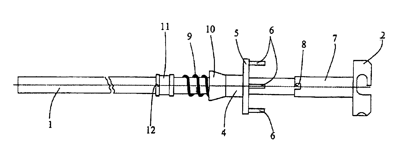
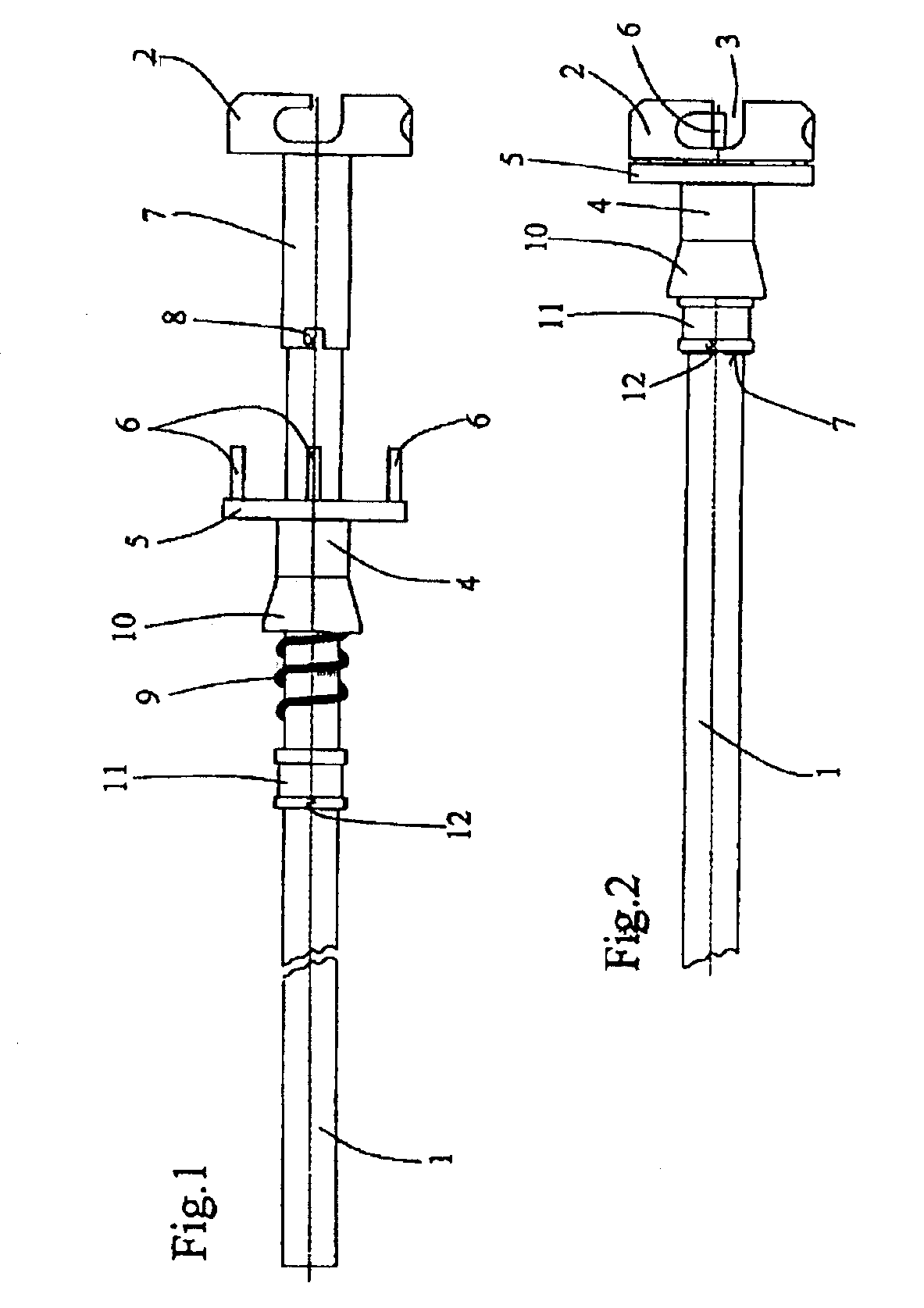
[0013]The instrument holder shown comprises a cylindrical shank 1 at one end of which a head 2 is fixed which is identical to the head described in U.S. Pat. No. 5,658,290, the content of which is incorporated by reference. This head has a central recess, the head forming a crown around this recess. This crown has four bayonet catches 3 diametrically opposite in pairs. A reamer analogous to the reamer shown and described in U.S. Pat. No. 5,658,290 is fixed in these catches 3. The reamer is locked in the catches 3 by an annular locking component 4 equipped with a plate 5 having four parallel fingers 6 which pass through the head 2 in order to close the bayonet catches 3, as is described in U.S. Pat. No. 5,658,290.

[0014]The locking component 4 does not slide directly on the section of the shank seen in FIG. 1, but on a section 7 with a greater diameter than the diameter of the rest of the shank. This section 7 can consist of a tubular component arranged on the shank 1. At least one b...


PUM


Abstract

Instrument holder comprising a shank (1) equipped with a head (2) designed to receive an instrument and a locking component (4) pushed against the head by a spring (9) bearing on a ring (11) sliding on the shank, and having means of connection (8, 12) on the shank which is engaged by rotation of the ring, in such a way that the release of the ring allows the locking component, the spring and the ring to slide freely in order to permit cleaning of the instrument holder.

Description

RELATED APPLICATIONS[0001]This application is a continuation of Ser. No. 09 / 902,369 filed on Jul. 9, 2001 now U.S. Pat No. 6,540,739, which in turn is a continuation of Ser. No. 09 / 602,341 filed Jun. 24, 2000 and now U.S. Pat. No. 6,264,647 issued Jul. 24, 2001.BACKGROUND OF THE INVENTION[0002]The invention relates to an instrument holder for a surgical instrument, comprising a shank equipped with a head designed to receive an instrument, and an annular locking component mounted so as to slide about the shank, under the head, equipped with locking means which cooperate with the head so as to lock the instrument on the head, and pushed against the head by a helical spring.[0003]An instrument holder of this type is known in particular from U.S. Pat. Nos. 5,658,290 and U.S. Pat. No. 5,236,433, the contents of which are incorporated by reference.[0004]A surgical instrument, for example for preparing for the fitting of a hip prosthesis, works in a medium which causes considerable soiling...

Claims


Application Information

Patent Timeline
IPC IPC(8): A61B17/00A61B17/16A61B90/00
CPCA61B17/1666A61B17/1617A61B2019/4868A61B2017/00477A61B2090/0813A61B17/162
Inventor LECHOT, ANDRE
Owner VIANT AS&O HLDG LLC
Why Eureka
Try Eureka