Device for correcting scoliosis and controlling vertebral arthrodesis

a technology for scoliosis and vertebrae, applied in the field of correcting scoliosis, can solve the problems of affecting the function of the vertebrae, and preventing the growth of the operated area,

Inactive Publication Date: 2013-12-19
UNIV CLAUDE BERNARD LYON 1 +1
View PDF0 Cites 19 Cited by
  • Summary
  • Abstract
  • Description
  • Claims
  • Application Information

AI Technical Summary

Benefits of technology

[0041]In accordance with this embodiment of the device of the invention, the device for locking the distraction device advantageously comprises two keepers that are movable in translation in the linking member in a direction parallel to the axes Xl, X2 in the linking member, said keepers being disposed either side of the suspension member and each bearing both on said suspension member and also on a distraction rod in order to lock it against sliding in a first direction relative to the linking member by an over-center effect while being capable of allowing it to slide freely in a second direction opposite to the first during stages of growth of a spine instrumented with the correction device.

Problems solved by technology

The principal disadvantage of such surgery is that it causes stiffening of the vertebral column and stops growth in the operated zone.
In addition, the surgery is not corrective but is palliative, fastening the column in the best possible position for the patient.
Such scolioses cannot be treated by conventional arthrodesis, which blocks the scoliosis but also blocks growth.
At the same time, orthopedic treatments carried out on such scolioses provide mediocre results.
However, a major disadvantage of that technique arises when the rods have to be lengthened as the implanted patients grow, and thus regular surgical procedures have to be carried out on the patients, approximately every 4 to 6 months, in order to change the rods or at the very least to lengthen them.
Those repeat interventions are difficult for the patient and family to accept; in addition, the force that has to be applied during each intervention in order to make the rod longer is proportional to the stiffening of the vertebral column, which loses its flexibility due to the scoliosis and also due to the immobility caused by the rod.
However, they also suffer from the same disadvantages as distraction rods, in particular the necessity for regular repeat surgical intervention in order to lengthen the implant to match the patient's growth.
That operational constraint, linked to the need to lengthen distraction rods and implants, has been the focus of several attempts at solutions; unfortunately, until now, none of them appears to have been shown to be effective.
That system, which in theory appears to be effective, is however very expensive, necessarily preventing any application thereof with a majority of patients.
However, that correction system has proved to be complex to produce and, despite its capacity for rod extension, it is extremely rigid; that may prove to be a problem for the patients.

Method used


Image

  • Device for correcting scoliosis and controlling vertebral arthrodesis
  • Device for correcting scoliosis and controlling vertebral arthrodesis
  • Device for correcting scoliosis and controlling vertebral arthrodesis

Examples


first embodiment

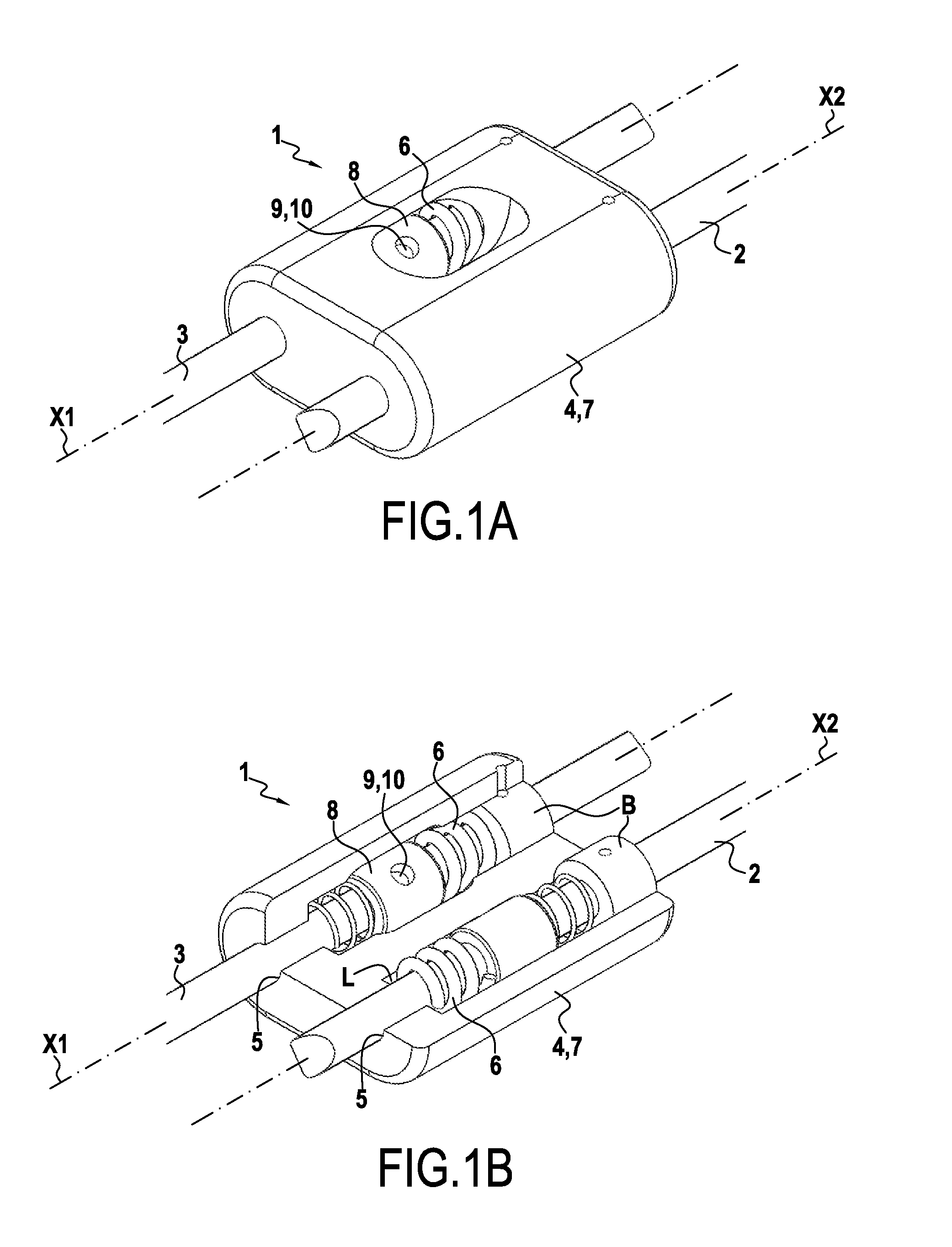
[0059]In a first embodiment shown in FIGS. 1A to 10, the correction device 1 comprises a casing 7 in which each of the two distraction rods 2, 3 of the correction device 1 is inserted along its own axis X1, X2, these two axes X1, X2 being parallel.

[0060]The casing 7 has a block-like, substantially parallelepipedal shape, in which two insertion and guiding channels 5 are formed for the distraction rods 2, 3 to slide therein. These two channels 5 are parallel and they both open out in the longitudinal direction of the casing 7, i.e. parallel to the distraction rods 2, 3.

[0061]Inside the casing 7, two cylindrical housings L are formed that are coaxial with the channels 5 for guiding the distraction rods 2, 3. Each housing L is for receiving and accommodating a suspension element 6 of the corresponding distraction rod 2, 3 and a structure for cushioning and locking the rod, here comprising a ring 8 for adjusting the travel of the distraction rod 2, 3 in the casing 7.

[0062]The housings L...

fourth embodiment

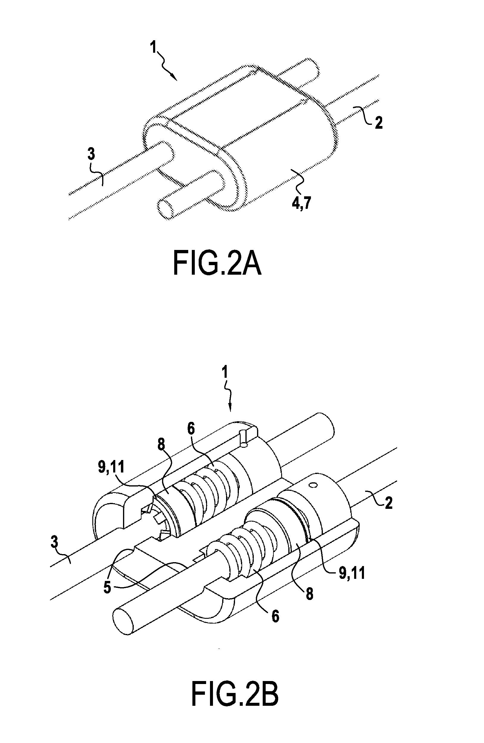
[0084]the correction device 1 of the invention, which is structurally analogous to the three embodiments described above, is presented in FIGS. 4A and 4B.

[0085]In this embodiment, the scoliosis correction device 1 comprises a linking member 4 formed by a casing 7 with a rectangular section in a plane containing the axes X1, X2 extending the distraction rods 2, 3 each inserted into apertures or channels formed along these parallel axes X1, X2 in two opposite walls of the of the casing 7. A rectangular housing is formed inside the casing 7. In this housing, the distraction rods 2, 3 extend along the axes X1, X2. Each of the rods 2, 3 cooperates with a cushioning and locking structure, here comprising a ring 8 and a suspension spring 6 threaded onto each distraction rod 2, 3. Inside the housing, the ring 8 and the spring 6 carried by the rod 2 are threaded onto it in a position that is reversed relative to the ring 8 and the spring 6 on the rod 3.

[0086]In this particular embodiment, ea...


PUM


Abstract

The present invention provides a scoliosis correction device comprising a pair of distraction rods (2, 3) and a member (4) for linking the distraction rods provided with means (8) for guiding each of the rods relative to each other inside said linking member. This device further comprises at least one member (6) for suspension of the distraction rods (2, 3) that can provide flexibility and exert a longitudinal pre-load on the rods in order to augment comfort and prevent vertebral arthrodesis of the spine of a patient instrumented with the correction device. Finally, it comprises a structure for cushioning and locking the distraction rods in translation in the linking member, said structure being active only when compressive forces are applied by the spine of a patient to the distraction rods (2, 3) so as to absorb and oppose said compressive forces and augment patient comfort, thereby preventing vertebral arthrodesis of the patient's spine.

Description

FIELD OF THE INVENTION[0001]The present invention relates to the field of correcting scoliosis, in particular infantile scoliotic pathologies.[0002]Scoliosis is a three-dimensional deformation of the vertebral column that usually occurs during growth. Severe scoliosis may result in substantial deformation with arthrosis, cardio-respiratory repercussions and esthetic unacceptability.[0003]Scoliosis progression is maximal during growth. It tends to become stabilized in the adult. The majority of treatments are thus directed towards children or adolescents. Severe forms require corseting treatment and sometimes surgical intervention.PRIOR ART[0004]Scoliosis surgery is known as vertebral arthrodesis. It is intended to lock the vertebrae together, stop progress and straighten the vertebral column as much as possible with the aid of metal rods attached to the column. The principal disadvantage of such surgery is that it causes stiffening of the vertebral column and stops growth in the ope...

Claims


Application Information

Patent Timeline
Patent Type & Authority Applications(United States)
IPC IPC(8): A61B17/70
CPCA61B17/7052A61B17/7047A61B17/7014A61B17/7025A61B17/7028A61B17/705
Inventor MASSENZIO, MICHELRONEL, SYLVIECUNIN, VINCENTBENNANI, ABDELKRIMJACQUELIN, ERICLAFON, YOANN
Owner UNIV CLAUDE BERNARD LYON 1
Why Eureka
Try Eureka