Continuously variable belt drive system

a belt drive and continuous variable technology, applied in the direction of gearing, gearing elements, hoisting equipment, etc., can solve the problems of unreasonably high electrical power requirements, heavy trucks cannot use electric motors to drive cooling fans, and achieve the effect of increasing the axial force generated by centrifugal movement of the weight arm and adequate axial for

Inactive Publication Date: 2007-05-15
BORGWARNER INC
View PDF13 Cites 21 Cited by
  • Summary
  • Abstract
  • Description
  • Claims
  • Application Information

AI Technical Summary

Benefits of technology

[0016]In one feature of the invention, one pulley assembly, preferably the driving assembly, includes a belt tensioning mechanism that maintains proper belt tension at any speed and pulley drive ratio. The mechanism can include a weight arm that is pivotably mounted to a floating sleeve. The forward and rear sheaves forming the driving pulley are mounted to the floating sleeve for rotation with the sleeve. The sleeve is splined to a rotating drive shaft so the sleeve can slide freely along the drive axis while rotational motion is transmitted to the sleeve. The floating sleeve allows the driving pulley to align itself with the driven pulley when the driven pulley adjusts the drive ratio.
[0017]Rotation of the floating sleeve causes the weight arm to swing radially outward due to centrifugal effects. The weight arm bears against a roller mounted on the rear sheave, thereby providing an axial force to push the rear sheave toward the relatively stationary forward sheave. As the floating sleeve and driving pulley rotate faster, the axial force generated by centrifugal movement of the weight arm increases.
[0018]In another aspect of the tensioning mechanism, a spring and lever arm configuration is used to maintain proper belt tension as the drive ratio changes. The mechanism uses a spring plate tending to push the rear sheave toward the forward sheave. When the rear sheave is in its forward-most position, a compression spring associated with the spring plate is only slightly depressed so its axial force is minimal. The present invention contemplates a lever arm disposed between the compression spring and the rear sheave that helps maintain adequate axial force even when the spring is at its minimum compression. The lever arm is pivotably mounted to the floating sleeve and includes a roller at its free end that bears against the rear sheave. The compression springs are retained between the floating sleeve and a spring plate that is free to slide axially relative to the driving pulley. The spring plate includes a roller that contacts a cam edge of the lever arm. Spring force is thus transmitted through the spring plate roller, to the lever arm and eventually to the rear sheave via another roller. The cam edge of the lever arm has a curvature that is calibrated to maintain the necessary axial force at all positions of the rear sheave, including its forward-most position.

Problems solved by technology

However, the bulk of the cooling requirements for the automotive vehicle is accomplished by air flowing through the engine compartment and across a radiator.
However, unlike passenger cars, heavy trucks cannot use electric motors to drive the cooling fan.
For a typical heavy truck, the cooling fan would require up to 50 horsepower to cool the engine, which translates to unreasonably high electrical power requirements.
Viscous drives suffer from many deficiencies.
For instance, drives of this type are inherently inefficient because a great amount of energy is lost in heating the viscous fluid.
For many viscous drives, this parasitic power loss can be as high as five horsepower.
Another difficultly experienced by viscous fluid fan drives is known as “morning sickness.” When the vehicle is started cold, the fluid in the fan drive is more viscous than under normal operating conditions.
A further problem with viscous fan drives is that they require a residual speed even when fully disengaged.
One problem exhibited by fixed pulley fan drives is that the fan speed is limited to the fixed ratio relative to the engine input speed.
Thus, a fan sized to cool an engine at a lower speed, such as 1200 r.p.m., is grossly oversized at higher engine operating speeds, such as a typical rated speed of 2100 r.p.m.
However, this over-sizing of the fan equates to wasted power when the engine is not operating at its peak torque condition.
Thus far, no accessory drive assemblies are known that are capable of achieving all of these features.
Although the continuously variable transmission has been beneficial in operation of cooling fans, the typical CVT cannot accomplish all of these particular factors.

Method used


Image

  • Continuously variable belt drive system
  • Continuously variable belt drive system
  • Continuously variable belt drive system

Examples


Embodiment Construction

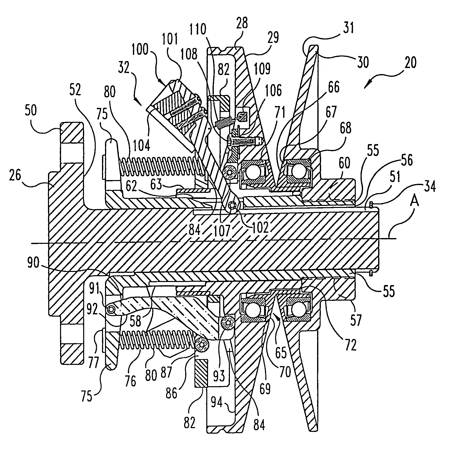
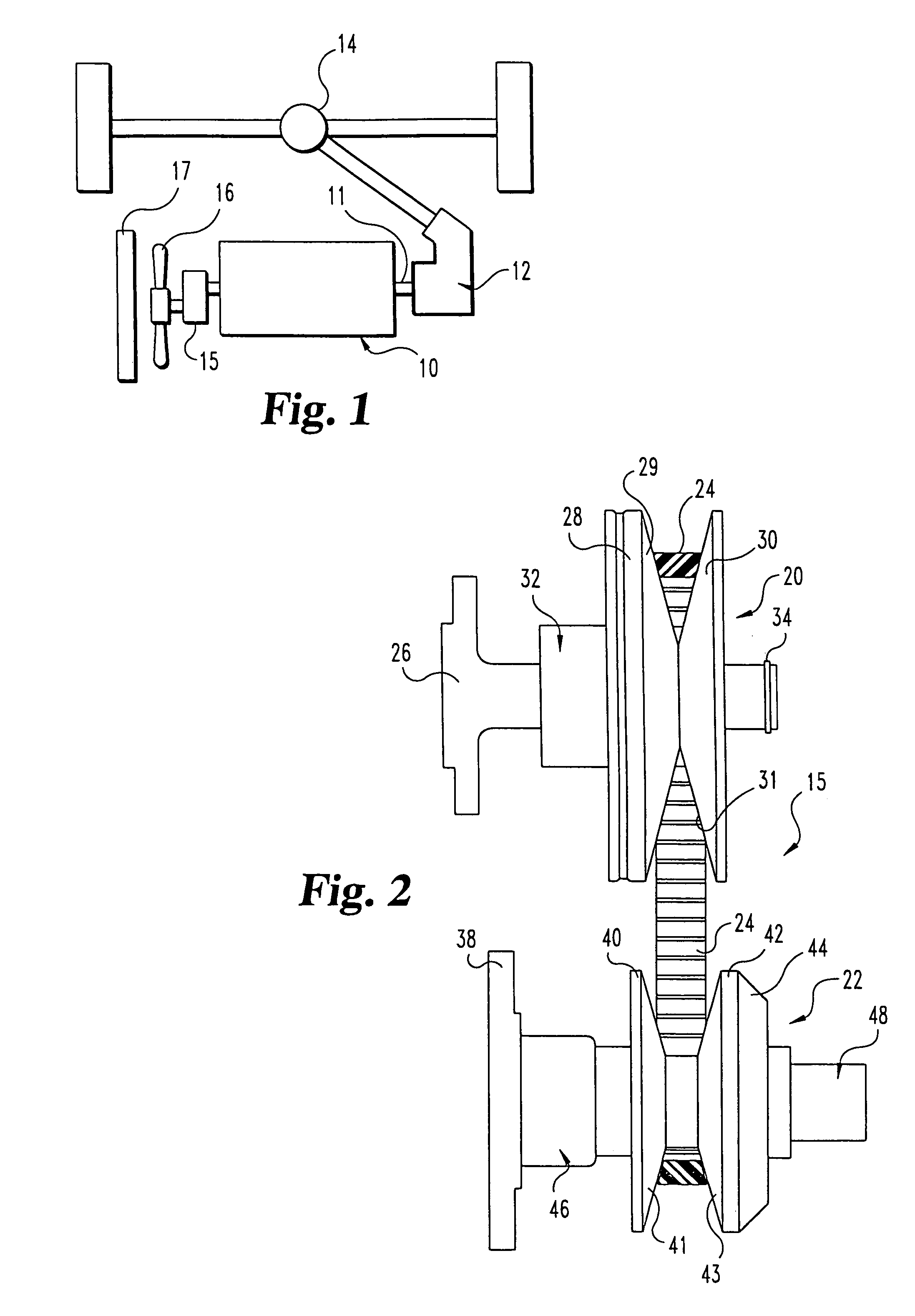
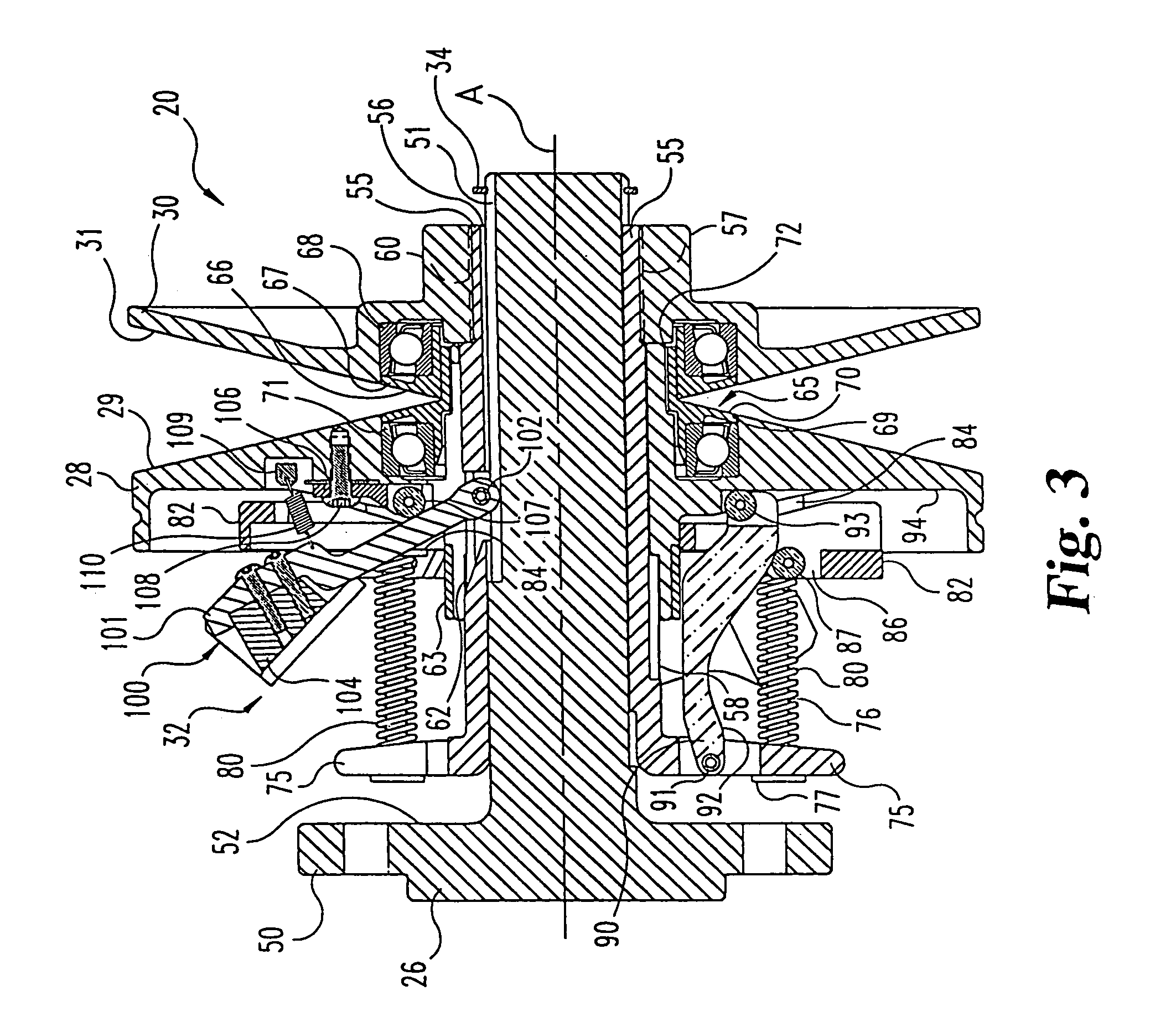
[0048]For the purposes of promoting an understanding of the principles of the invention, reference will now be made to the embodiments illustrated in the drawings and specific language will be used to describe the same. It will nevertheless be understood that no limitation of the scope of the invention is thereby intended. The invention includes any alternations and further modifications in the illustrated devices and described methods and further applications of the principles of the invention which would normally occur to one skilled in the art to which the invention relates.

[0049]The present invention concerns a continuously variable transmission, or transfer drive assembly, particularly suited for driving auxiliary devices in an automotive vehicle. Of course, the principles of the invention can be employed in a variety of applications where continuously or infinitely variable speed ratios are desired.

[0050]In general terms, the invention provides a driving member assembly that i...


PUM


Abstract

A continuously variable belt drive system including a driving pulley assembly, a driven pulley assembly, and a V-shaped belt engaged to transfer rotary power therebetween is disclosed herein. The driving pulley assembly includes an idler pulley portion. As the belt speed decreases, the belt migrates downward within the driving pulley assembly until it falls within the idler pulley portions, thereby isolating the belt from the rotation of the driving pulley assembly. The driving pulley assembly also includes a belt tensioning mechanism that maintains proper belt tension at all speeds and drive ratios. The tensioning mechanism relies upon a pivotably mounted centrifugal weight arm to provide tensioning as a function of speed. A compression spring provides axial pressure to maintain belt tension over all drive ratios. The spring, acts against a curved cam edge on a pivoting lever arm, which arm transfers an axial force to the rear sheave of the driven pulley assembly.

Description

CROSS-REFERENCE TO RELATED APPLICATIONS[0001]This is a division of U.S. patent application Ser. No. 09 / 973,373, filed on Oct. 9, 2001 and issued as U.S. Pat. No. 6,962,543, which is a division of U.S. patent application Ser. No. 09 / 405,188, filed on Sep. 24, 1999 and issued as U.S. Pat. No. 6,406,390BACKGROUND OF THE INVENTION[0002]The present invention concerns a continuously variable transfer drive assembly or transmission mechanism, such as the type suited for use in automotive applications to drive accessory devices. More particularly, the invention relates to a mechanically adjustable belt-type pulley system.[0003]Automotive vehicles include a cooling system to dissipate heat developed by the vehicle power plant, such as an internal combustion engine. In a typical automotive vehicle, the lubrication system provides some cooling function as hot lubricant is pumped away from the engine. However, the bulk of the cooling requirements for the automotive vehicle is accomplished by ai...

Claims


Application Information

Patent Timeline
Patent Type & Authority Patents(United States)
IPC IPC(8): F16H59/10F16H55/00F16H55/56F16H61/12F16H63/06
CPCF16H55/56F16H55/563F16H63/062F16H63/067F16H61/12
Inventor ROBY, JOSHUA L.
Owner BORGWARNER INC
Why Eureka
Try Eureka