Peripheral circuit structure

a peripheral circuit and circuit technology, applied in the field of peripheral circuit structure, can solve the problems of easy damage to the peripheral circuit structure by the esd, high risk of malfunction, and low resistance so as to improve the ability of the peripheral circuit structure to resist the esd, and improve the reliability of the integrated circui

Inactive Publication Date: 2014-05-22
WINTEK CORP
View PDF1 Cites 29 Cited by
  • Summary
  • Abstract
  • Description
  • Claims
  • Application Information

AI Technical Summary

Benefits of technology

[0023]Accordingly, in the present invention, the traces (including the first trace and the second trace) and the ground pads (including the first ground pad and the second ground pad) which are electrically connected with each other contributes to increasing paths of currents flowing through where the traces and the ground pads are connected and effect...

Problems solved by technology

Generally, damages caused by the electrostatic discharge (ESD) possibly happen to an electronic product at any time when being manufactured, packaged, tested, delivered, even finally shipped and used, which leads to high risk of malfunction.
However, the traces and the pads have different resistances, such that once an instantaneous current fai...

Method used


Image

  • Peripheral circuit structure
  • Peripheral circuit structure
  • Peripheral circuit structure

Examples


Embodiment Construction

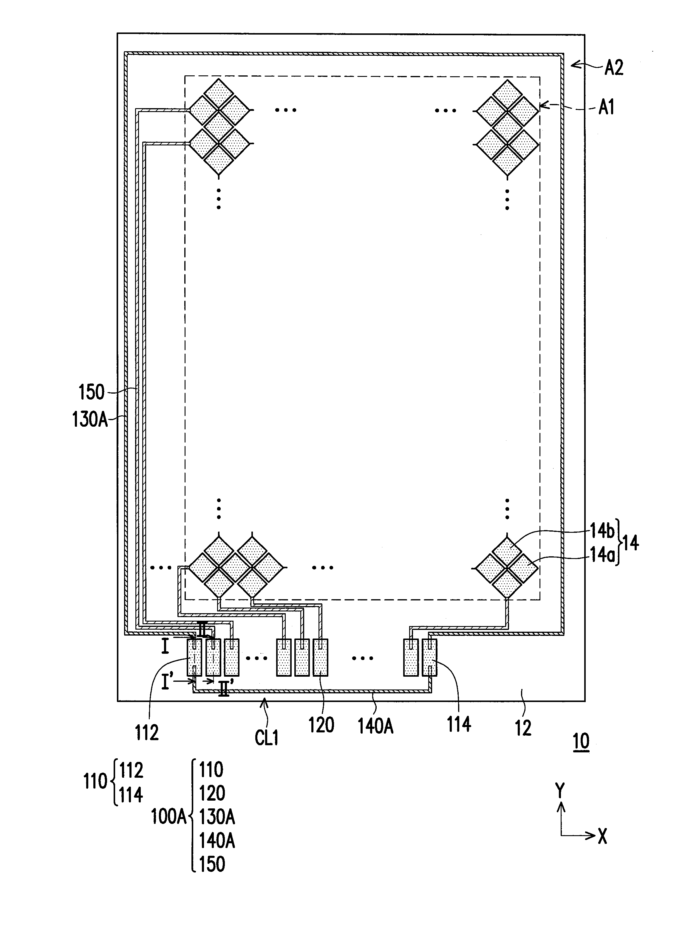
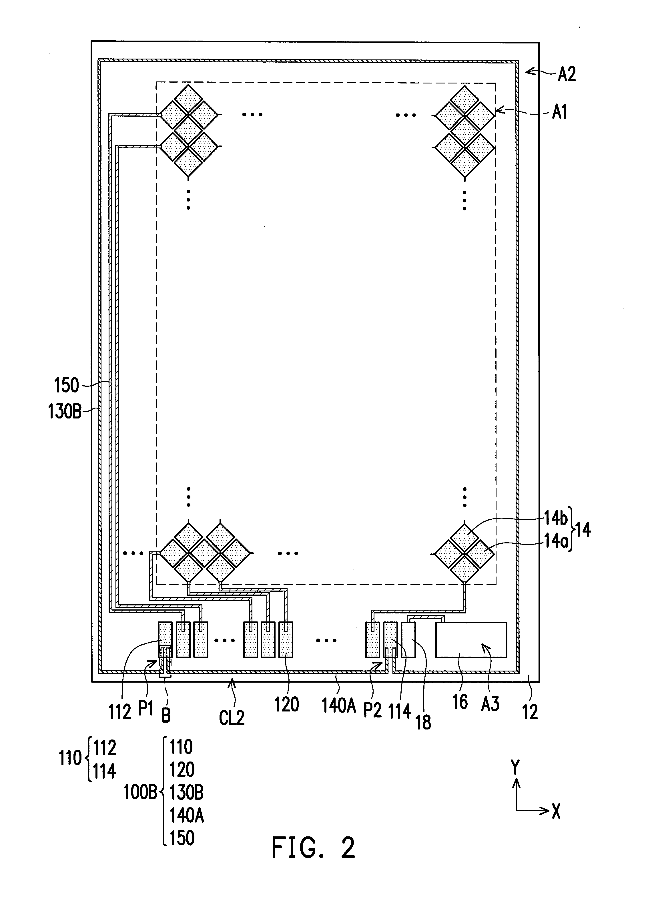
[0031]FIG. 1 through FIG. 6 are schematic top views illustrating a touch panel applying peripheral circuit structures according to different embodiments of the present invention. Referring to FIG. 1, a peripheral circuit structure 100A of the present embodiment may be applied in a touch panel 10, for example, wherein the touch panel 10 includes a substrate 12. In the present embodiment, the peripheral circuit structure 100A is disposed on the substrate 12.

[0032]In detail, the substrate 12 includes an element region A1 and a peripheral circuit region A2 surrounding the element region A1. The peripheral circuit structure 100A is disposed in the peripheral circuit region A2, and at least one element 14 is disposed in the element region A1.

[0033]In the present embodiment, the device 14 is, for example, a touch sensing element, and a plurality of touch sensing elements are arranged in an array in the element region A1. A decoration layer is disposed on the peripheral circuit region A2 to...


PUM


Abstract

A peripheral circuit structure disposed on a substrate having an element region and a peripheral circuit region is provided. The peripheral circuit structure located in the peripheral circuit region includes first pads, second pads, a first trace, a second trace and third traces connected to the second pads and a device located in the element region. The first pads include a first ground pad and a second ground pad. The second pads are located between the first ground pad and the second ground pad. Two ends of the first trace are respectively electrically connected to the first ground pad and the second ground pad. Two ends of the second trace are respectively electrically connected to the first ground pad and the second ground pad, so that the second trace, the first trace, the first ground pad and the second ground form a closed loop.

Description

CROSS-REFERENCE TO RELATED APPLICATION[0001]This application claims the priority benefit of Taiwan application serial no. 101143709, filed on Nov. 22, 2012. The entirety of the above-mentioned patent application is hereby incorporated by reference herein and made a part of this specification.BACKGROUND[0002]1. Field of the Invention[0003]The present invention is directed to a peripheral circuit structure and more particularly, to a peripheral circuit structure contributing to improving the capability for resisting electrostatic discharge (ESD).[0004]2. Description of Related Art[0005]Generally, damages caused by the electrostatic discharge (ESD) possibly happen to an electronic product at any time when being manufactured, packaged, tested, delivered, even finally shipped and used, which leads to high risk of malfunction. Thus, the electronic product has to be designed with an ESD protection capability for prolonging the lifespan of the electronic product.[0006]In a manufacturing pro...

Claims


Application Information

Patent Timeline
IPC IPC(8): H05K1/02
CPCH05K1/0259H05K1/117H05K2201/09354H05K2201/09781H05K2201/0979H05K1/0215H05K2201/0326H05K2201/09227H05K2201/09418H05K2201/09681G06F3/041G06F3/04164G06F3/0446G06F2203/04107G06F2203/04103
Inventor LI, CHUNG-HSIENCHEN, KUO-HSINGCHEN, YU-TINGSU, CHEN-HAO
Owner WINTEK CORP
Why Eureka
Try Eureka