Projector

a projector and projector technology, applied in the field of projectors, can solve the problems of inability to directly use the configuration and arrangement of the cooling unit known in the past, and the inability to separate color light into a plurality of color lights, so as to improve the appearance characteristics of the projector and improve the cooling efficiency

Active Publication Date: 2014-05-22
SEIKO EPSON CORP
View PDF4 Cites 12 Cited by
  • Summary
  • Abstract
  • Description
  • Claims
  • Application Information

AI Technical Summary

Benefits of technology

[0052]The projector cover has the shape in which the end on the projecting direction side is located further on the connecting unit side than the end on the projecting direction side of the cover. Therefore, the warmed air discharged from the opening section of the projector cover is suppressed from being led into the opening section of the cover. Therefore, it is possible to further improve cooling efficiency for the projector.
[0053]Since the projector includes the projector cover, it is more likely that the projector is observed as an interior by a user. Therefore, even when the projector is attached to a bulb socket not provided with a socket cover, it is possible to improve the appearance characteristics of the projector.

Problems solved by technology

Therefore, it is difficult to directly use the configuration and the arrangement of the cooling unit known in the past.
Further, a configuration for separating color light into a plurality of color lights is unnecessary.

Method used


Image

  • Projector
  • Projector
  • Projector

Examples


first embodiment

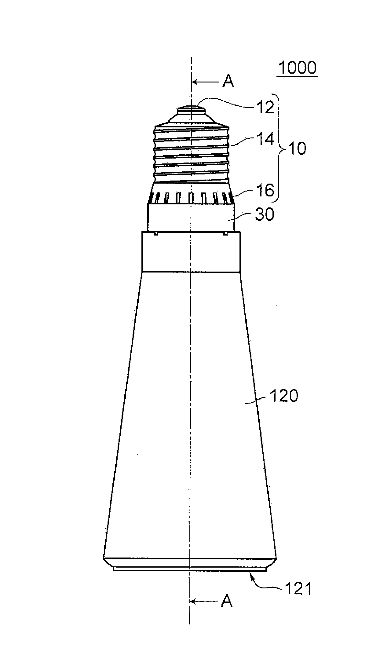
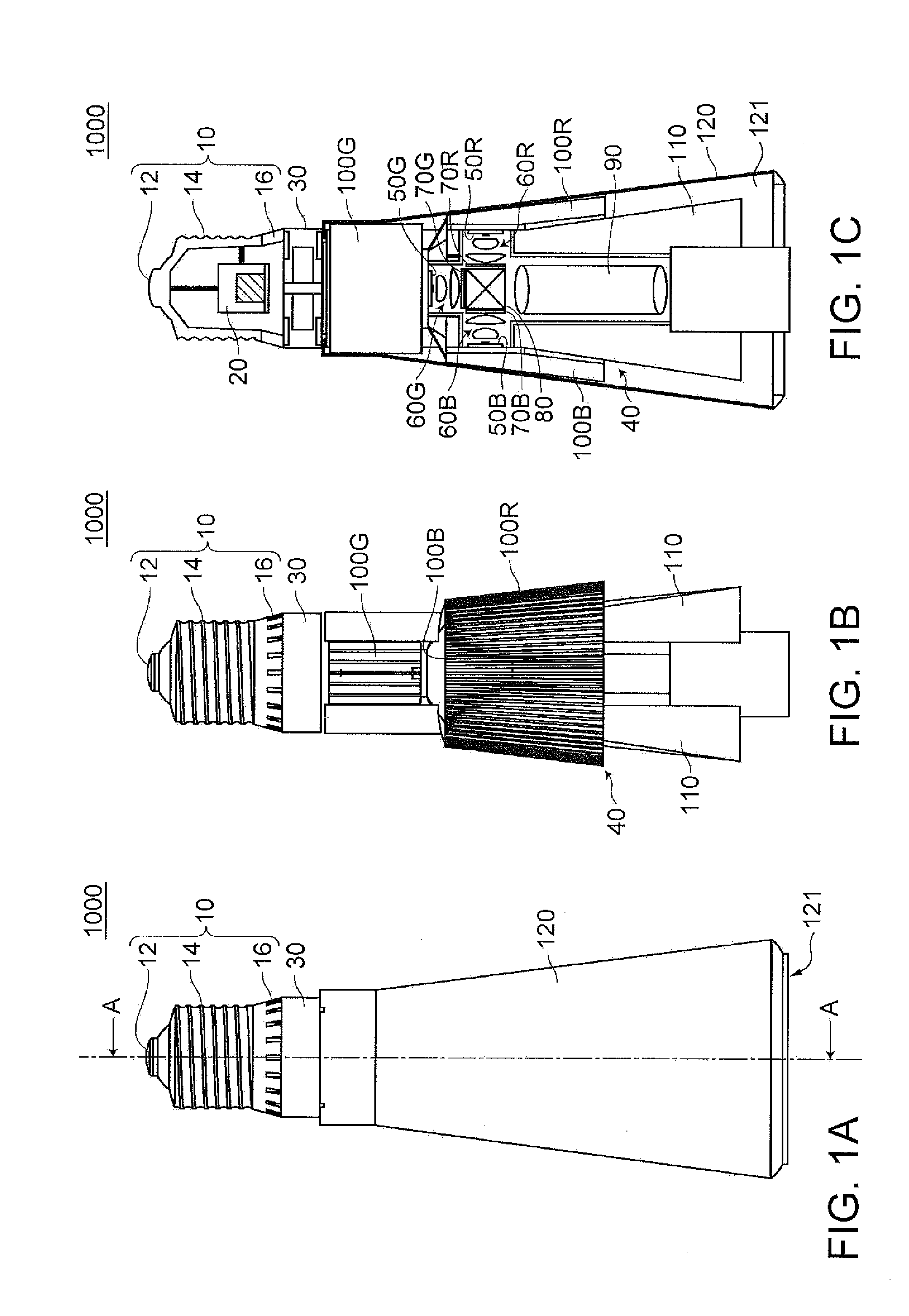
[0075]FIGS. 1A to 1C are schematic diagrams for explaining a projector 1000 according to a first embodiment. Specifically, FIG. 1A is a front view of the projector 1000. FIG. 1B is a front view of the projector 1000 in a state in which a cover 120 included in the projector 1000 is removed. FIG. 1C is an A-A sectional view of FIG. 1A.

[0076]The projector 1000 includes, as shown in FIGS. 1A to 1C, a connecting unit 10, a power supply unit 20, a cooling unit 30, an optical engine unit 40, and the cover 120.

[0077]The connecting unit 10 is configured to be connectable to a bulb socket to which electric power is supplied from the outside. Further, the connecting unit 10 includes a first contact portion 12 located in a distal end portion and a second contact portion 14 on which a spiral thread (a right-hand thread) is formed. The connecting unit 10 in this embodiment corresponds to a screw-type bulb socket specified by a model number E26 standardized by the TEC (International Electrotechnic...

second embodiment

[0127]A projector 1002 according to a second embodiment basically has a configuration same as the configuration of the projector 1000 according to the first embodiment. However, the projector 1002 includes a cooling unit 32 having a configuration different from the configuration of the cooling unit 30 in the projector 1000 according to the first embodiment.

[0128]FIG. 7 is a schematic diagram for explaining the projector 1002 according to the second embodiment. In FIG. 7, curved line arrows indicated by sign F represent schematic flows of the air.

[0129]As shown in FIG. 7, the cooling unit 32 in the projector 1002 according to this embodiment is configured to form a flow of the air from the connecting unit 10 side to the optical engine unit 40 side.

[0130]That is, the cooling unit 32 forms the flow of the air in a direction opposite to the direction of the flow of the air formed by the cooling unit 30 in the first embodiment. Specifically, the air outside the projector 1002 is led in f...

third embodiment

[0134]A projector 1004 according to a third embodiment includes an extension member 124 not included in the projector 1000 according to the first embodiment and includes a cover 122 formed to allow the extension member 124 to be attached and detached.

[0135]FIGS. 8A to 8D are schematic diagrams for explaining the projector 1004 according to this embodiment. Specifically, FIG. 8A is a sectional view of the projector 1004 in a state in which the extension member 124 is not attached. FIG. 8B is a sectional view of the projector 1004 in a state in which the extension member 124 is attached. FIG. 8C is a sectional view of the extension member 124. FIG. 8D is a perspective view of the extension member 124.

[0136]The cover 122 has a configuration same as the configuration of the cover 120 in the first embodiment. However, the cover 122 is different from the cover 120 in that the cover 122 includes, at an end on an opening section 1221 side, a fixing section 123 configured to engage with the ...


PUM


Abstract

A projector includes an optical engine unit including a light source unit configured to emit light, a light modulating unit configured to modulate, according to image information, the light emitted from the light source unit, and a projecting unit configured to project the light modulated by the light modulating unit, a connecting unit connectable to a bulb socket, a power supply unit configured to supply electric power received from the connecting unit to the optical engine unit, and a cooling unit arranged between the connecting unit and the optical engine unit and configured to circulate the air to cool the power supply unit and the optical engine unit.

Description

BACKGROUND[0001]1. Technical Field[0002]The present invention relates to a projector.[0003]2. Related Art[0004]There has been widely known a projector including a cooling unit configured to circulate the air to cool an internal mechanism (see, for example, JP-A-2005-31106). In the projector in the past, it is possible to cool, with the cooling unit, the internal structure (e.g., a power supply unit and an optical engine unit) of the projector.[0005]However, the widely-known projector in the past is a general projector that uses electric power from a battery, a socket, or the like. Naturally, there are known the configuration and the arrangement of the cooling unit corresponding to the projector. Therefore, concerning a projector that uses electric power supplied from a bulb socket, i.e., a projector connected to the bulb socket and used, the projector including the cooling unit and the configuration and the arrangement of the cooling unit are not known. Concerning the projector conn...

Claims


Application Information

Patent Timeline
Patent Type & Authority Applications(United States)
IPC IPC(8): G03B21/16
CPCG03B21/16G03B21/145G03B21/2013G03B33/06G03B21/20G03B21/2006G03B21/2033G03B21/208H04N9/3144
Inventor NAGATANI, KANAME
Owner SEIKO EPSON CORP
Why Eureka
Try Eureka