Floating flap gate

a technology of floating flap gate and flap body, which is applied in the field of floating flap gate, can solve the problems of floating flap gate disclosed in patent reference 2, which is not readily lower, and the ability of the door body so as to reduce the shock and improve the effect of the ability to follow the water level

Active Publication Date: 2014-05-22
HITACHI ZOSEN CORP
View PDF7 Cites 29 Cited by
  • Summary
  • Abstract
  • Description
  • Claims
  • Application Information

AI Technical Summary

Benefits of technology

[0014]According to the present invention, the predetermined angle of inclination of the door body with respect to a horizontal plane while raising or lowering the door body serves as a point of bifurcation for assisting in raising and lowering the door body and, causing resistance to raising or lowering the door body, thus making it possible to prevent water from overflowing at the time of the initial influx, and also making it possible to prevent the door from suddenly falling before lowering of the door body is completed. In addition, it becomes possible to mitigate the shock which occurs when raising of the door body is completed, and the ability of the door body to follow the water level improves at the initial stage of lowering of the door body.

Problems solved by technology

However, the floating flap gate disclosed in Patent Reference 1 has a problem in that if a speed of the inflowing water is high, the rising action of a door body 1 is delayed, resulting in an overflow of water into living spaces or underground spaces (see FIG. 11 (a).)
In addition, when the water level drops, the door body 1 stays at a rising state up to a water level which is about ⅓ the height of the door body 1, and subsequently exhibits a hazardous behavior such as suddenly falling (see FIG. 11 (b).)
However, the floating flap gate disclosed in Patent Reference 2 does not readily lower when the water level drops, because weight of the counterweight continually operates in a direction which assists in the operation of raising the door body.

Method used


Image

  • Floating flap gate
  • Floating flap gate
  • Floating flap gate

Examples


example

[0027]An example of the present invention is described in detail below using FIG. 1 to FIG. 10.

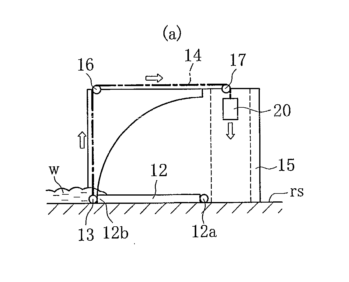
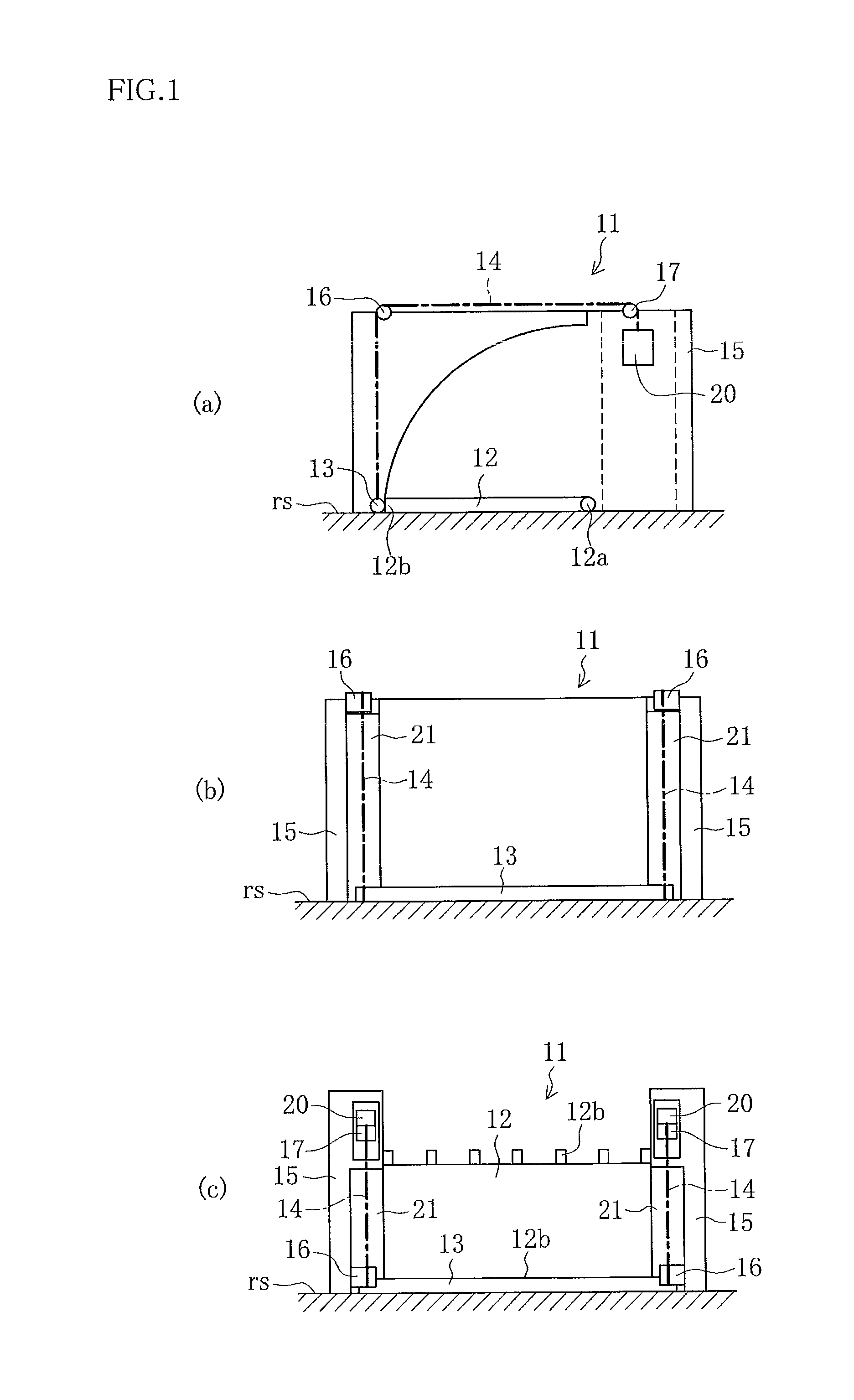
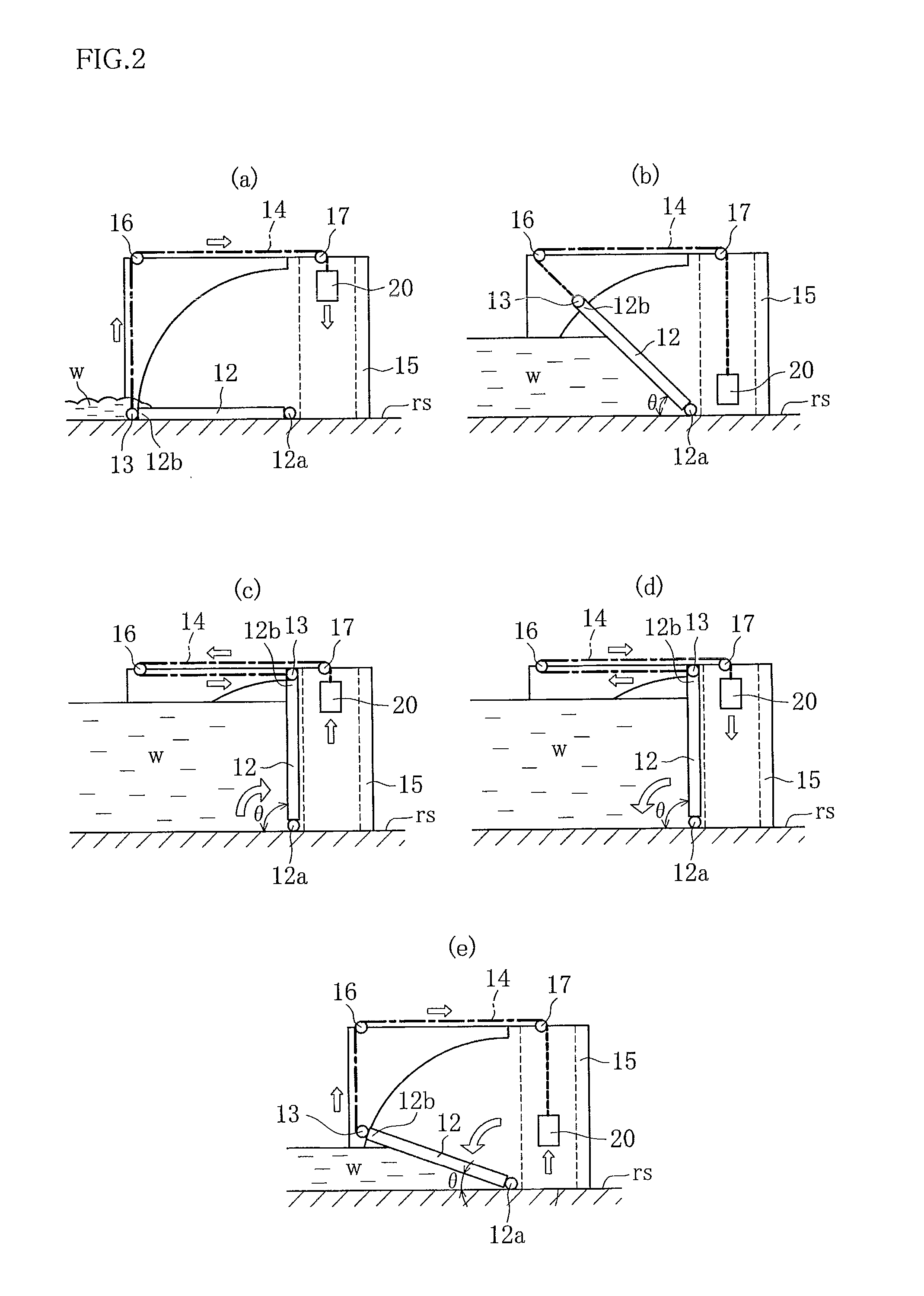
[0028]FIG. 1 is a schematic structural drawing of the floating flap gate according to the present invention.

[0029]In FIG. 1, Reference Numeral 11 is a floating flap gate according to the present invention which is disposed on a channel surface rs at an opening in a seawall, for example. When a water w tries to flow from an ocean (or from a river) into a living space or an underground space, the floating flap gate 11 uses the pressure of the water w to swing a forward end 12b of a door body 12 upwards around a base end 12a as a fulcrum, to block the opening in a water-tight manner.

[0030]If there is a wide opening to be blocked by the door body 12 of the floating flap gate 11, then a plurality of door bodies 12 may be linked width-wise at the opening, and the spaces between the various door bodies 12 are joined together with water-tight rubber. In addition, water-tight rubber is provided on ...


PUM


Abstract

The object of the present invention is to prevent an overflow of water into living spaces and underground spaces, to prevent difficulties in lower the door body when the water level has dropped, and to prevent the door body from suddenly falling. This is achieved by a floating flap gate 11 which is disposed at an opening or at an access way, so as to block the opening or the access way when water w flows in, and comprises a door body 12 with a forward end which is able to swing upwards, within in a plane in a height direction in a direction in which the water flows in around a base end thereof serving as a fulcrum. A rod 13 is attached to the forward end of the door body 12. One end of a wire rope 14 is attached to the rod 13, and the other end is attached to a counterweight 20 via fixed pulleys 16, 17. The fixed pulley 16 is arranged so that the counterweight 20 is at its lowest point when the angle of inclination of the door body 12 with respect to a horizontal plane reaches within a range from 10° to 80° during raising or lowering of the door body 12.

Description

TECHNICAL FIELD[0001]The present invention relates to a floating flap gate which is disposed at an opening in a seawall to prevent a rising water from flowing into living spaces or underground spaces at a time of rising water, by raising a door body to block the opening.BACKGROUND ART[0002]A floating flap gate exists which is disposed at an opening of a seawall and blocks the opening at the time of a rising water to prevent the rising water from flowing into living spaces or underground spaces, by raising a door body, using a buoyancy of the water which is trying to flow in (e.g., Patent Reference 1).[0003]However, the floating flap gate disclosed in Patent Reference 1 has a problem in that if a speed of the inflowing water is high, the rising action of a door body 1 is delayed, resulting in an overflow of water into living spaces or underground spaces (see FIG. 11 (a).)[0004]In addition, when the water level drops, the door body 1 stays at a rising state up to a water level which i...

Claims


Application Information

Patent Timeline
Patent Type & Authority Applications(United States)
IPC IPC(8): E02B7/40
CPCE02B3/104E02B7/44E06B2009/007E02B7/50E06B5/00E02B7/40
Inventor NAKAYASU, KYOUICHIYAMAKAWA, YOSHITOMORII, TOSHIAKIINUI, MASAKIKIMURA, YUUICHIROU
Owner HITACHI ZOSEN CORP
Why Eureka
Try Eureka