Integrated ultrasonic-inductive pulse sensor for wear debris detection

a technology of wear debris and pulse sensor, which is applied in the direction of suspension, porous material analysis, material impedance, etc., can solve the problems of small wear particles breaking off from machine components and building up in oil, increasing the particle population and particle size, and taking time to generate wear information

Active Publication Date: 2014-05-29
THE UNIVERSITY OF AKRON
View PDF8 Cites 14 Cited by
  • Summary
  • Abstract
  • Description
  • Claims
  • Application Information

AI Technical Summary

Problems solved by technology

Over time, small wear particles break off from machine components and build up in the oil.
The particle population and size of the particles tends to increase over time until eventually, a machine failure can result.
However, each of these methods takes time to generate wear information.
As a result

Method used


Image

  • Integrated ultrasonic-inductive pulse sensor for wear debris detection
  • Integrated ultrasonic-inductive pulse sensor for wear debris detection
  • Integrated ultrasonic-inductive pulse sensor for wear debris detection

Examples


first embodiment

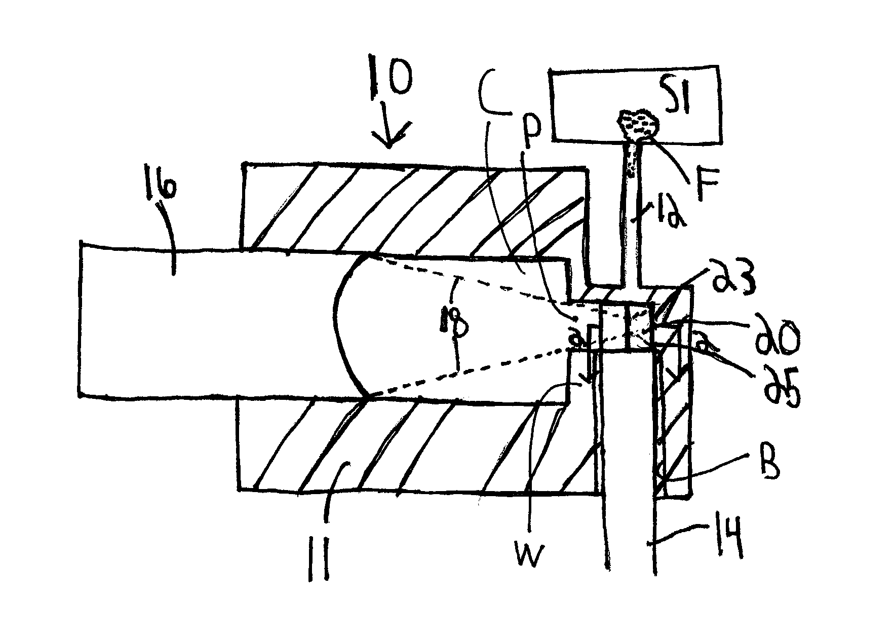
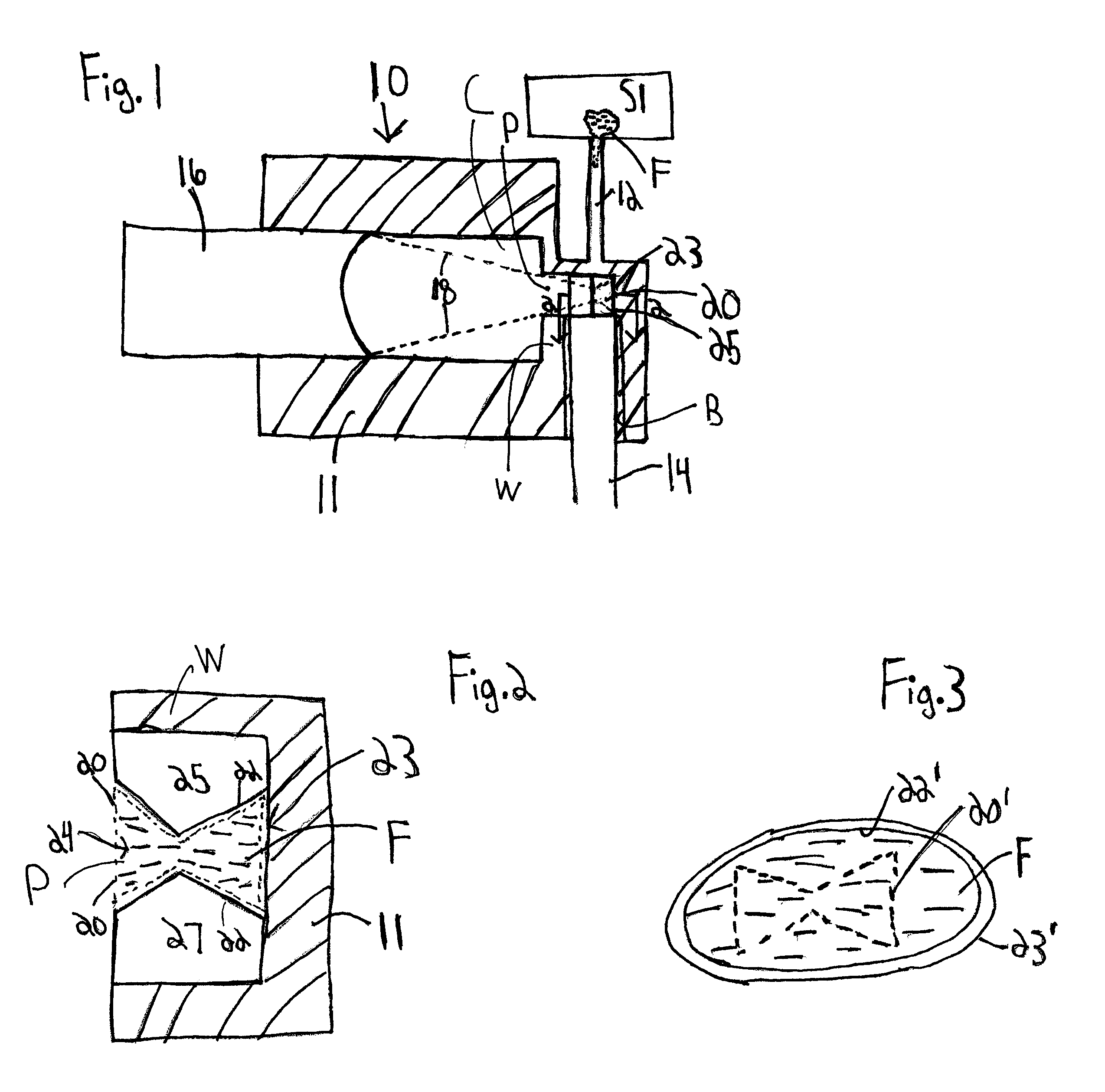
[0030]With reference to FIGS. 1 and 2, this invention provides an apparatus 10 for the detection of wear particles in a fluid. The apparatus 10 includes a housing 11 having a through bore B that receives an inlet channel 12 and an outlet channel 14 with a flow path 22 defined by a flow path structure 23 between the inlet channel 12 and outlet channel 14. Fluid F having wear particles therein is fed into the inlet channel 12 from a source S1 and flows from the inlet channel 12 to the outlet channel 14 through the flow path 22. The housing 11 further includes a transducer chamber C that receives an ultrasonic transducer 16. The transducer chamber C communicates with the through bore B through a wave passage P in a wall W between the through bore B and the transducer chamber C. The ultrasonic transducer 16 creates an acoustic wave 18 that defines an acoustic focal zone 20 at the flow path 22. The flow path 22 is shaped to restrict the flow of the fluid F to be wholly within the acousti...

second embodiment

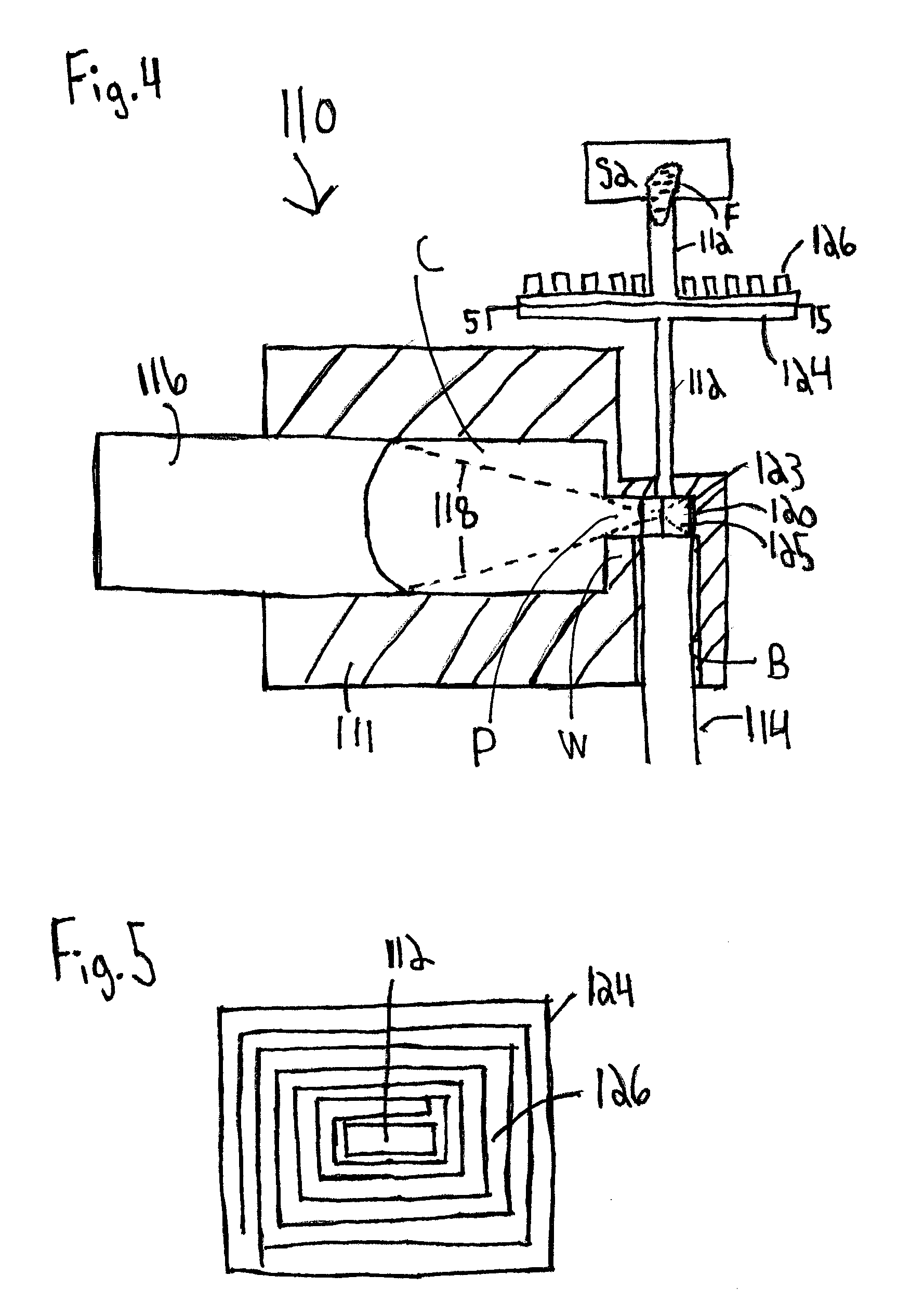
[0036]With reference to FIG. 4, this invention provides an apparatus 110 for the detection of wear particles in a fluid F. This apparatus is substantially like that of FIGS. 1 and 2 though an inductive pulse sensor is added upstream of the flow path 122 at which the ultrasonic transducer 116 acts to analyze wear particulate data. Thus, the apparatus 110 includes a housing 111 having a through bore B that receives an inlet channel 112 and an outlet channel 114, with a flow path 122 defined by a flow path structure 123 between the inlet channel 112 and outlet channel 114. Fluid F having wear particles therein is fed into the inlet channel 112 from a source S2 and flows from the inlet channel 112 to the outlet channel 114 through the flow path 122. The housing 111 further includes a transducer chamber C that receives an ultrasonic transducer 116. The transducer chamber C communicates with the through bore B through a wave passage P in a wall W between the through bore B and the transdu...

third embodiment

[0041]With reference to FIG. 6, this invention provides an apparatus 210 for the detection of wear particles in a fluid F. This apparatus is substantially like that of FIGS. 3 and 4, though the inductive pulse sensor 224 is positioned downstream of the flow path 222 at which the ultrasonic transducer 126 acts to analyze wear particulate data. Thus, the apparatus 210 includes a housing 211 having a through bore B that receives an inlet channel 212 and an outlet channel 212, with a flow path 222 defined by a flow path structure 23 between the inlet channel 212 and the outlet channel 214. Fluid F having wear particles therein is fed into the inlet channel 212 from a source S3 and flows from the inlet channel 212 to the outlet channel 214 through the flow path 222. The housing 211 further includes a transducer chamber C that receives an ultrasonic transducer 216. The transducer chamber C communicates with the through bore B through a wave passage P in a wall W between the through bore B...


PUM


Abstract

An apparatus for detecting wear particles in a fluid includes an inlet channel and an outlet channel. An ultrasonic transducer creating an acoustic wave that defines an acoustic focal zone is located between the inlet and outlet channels. A flow path located between the inlet and outlet channel is shaped to restrict the flow of the fluid to be within the acoustic focal zone. An inductive pulse sensor includes a plurality of flow channels receiving the fluid and a plurality of planar coils wound around the flow channels. The inductive pulse sensor includes a detection system for the detection of wear particles passing through the flow channels based on a change in an electrical property of the planar coils. A single combined excitation signal is sent to all the planar coils at once and the detection system measures one single output measurement for the plurality of flow channels.

Description

CROSS-REFERENCE TO RELATED APPLICATIONS[0001]This application claims the benefit of U.S. provisional patent application Ser. No. 61 / 730,225 entitled “An Integrated Ultrasonic-Inductive Pulse Sensor for Wear Debris Detection,” filed Nov. 27, 2012, and incorporated by reference in its entirety.FIELD OF THE INVENTION[0002]The present invention generally relates to an apparatus and a method for detection of wear particles in a lubricant. Some embodiments relate to an apparatus employing an ultrasonic transducer to detect wear particles in a fluid forced to flow through a focal zone of the ultrasonic wave generated by the transducer. Other embodiments relate to an apparatus employing an inductive pulse sensor multiplexed and multichannel detection. More particularly, the present invention relates to an apparatus and method of detecting wear particles in a lubricant which uses both an ultrasonic detection means which employs a multiplexed and multichannel detection means, and an inductive...

Claims


Application Information

Patent Timeline
IPC IPC(8): G01N27/02
CPCG01N27/023G01N29/024G01N29/222G01N33/2888G01N2291/02416
Inventor ZHE, JIANGDU, LI
Owner THE UNIVERSITY OF AKRON
Why Eureka
Try Eureka