Axle support structures for industrial vehicles

a technology for axle support and industrial vehicles, applied in axle units, rigid suspensions, transportation and packaging, etc., can solve the problems of large number of components of axle support structures and a large amount of production man-hours, so as to reduce the number of components required, reduce production man-hours, and facilitate formation

Active Publication Date: 2014-05-29
TOYOTA IND CORP
View PDF11 Cites 6 Cited by
  • Summary
  • Abstract
  • Description
  • Claims
  • Application Information

AI Technical Summary

Benefits of technology

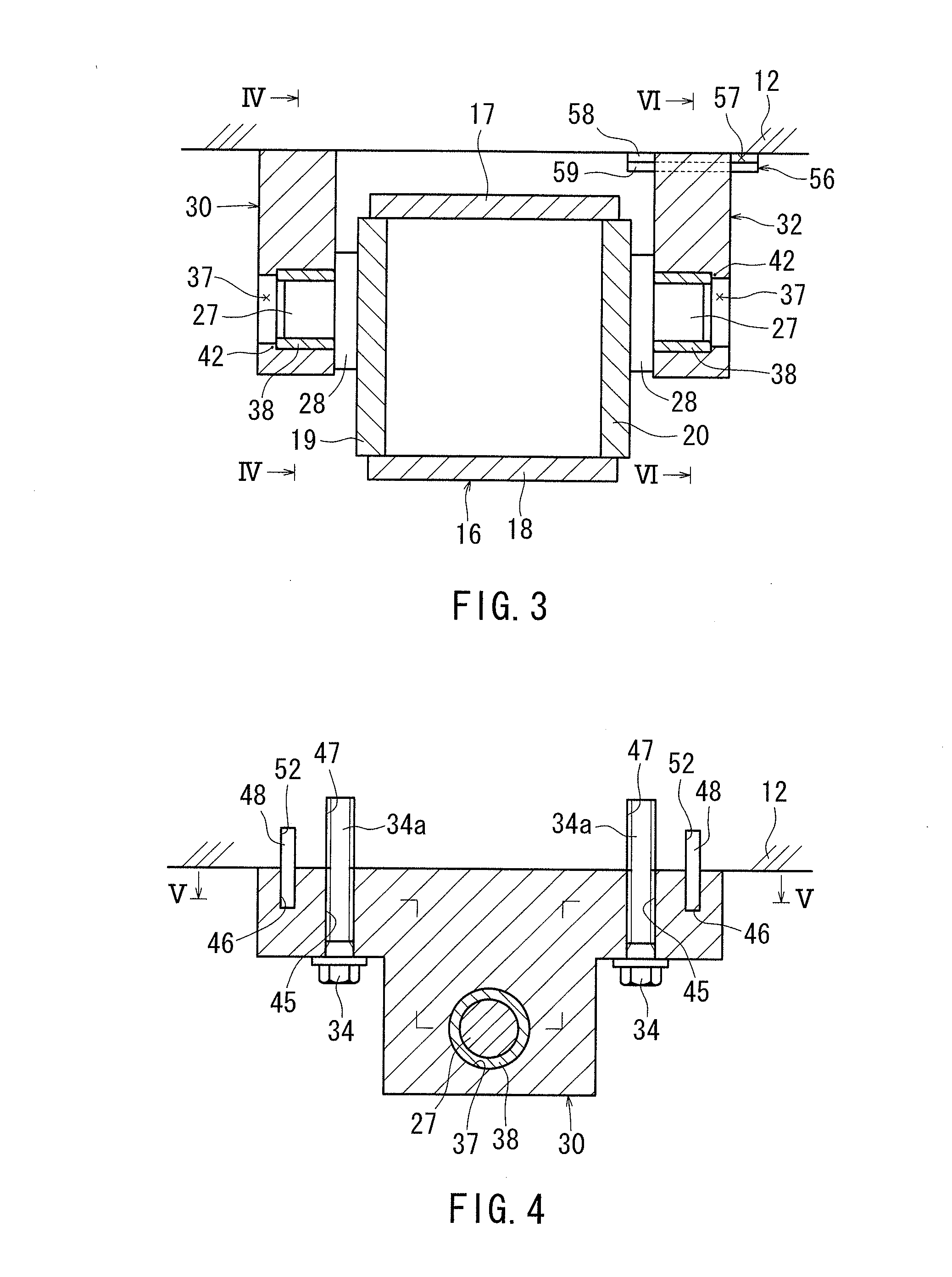
[0013]Accordingly, it is possible to omit the conventionally needed detachment prevention plate. Or, there is no need to weld a detachment prevention plate to the upper or lower support member. As a result, it is possible to reduce the number of components required for bearing detachment prevention or to reduce the production man-hours.
[0014]In another aspect of the invention, at the end portion of the support hole opposite to the entrance, a jig opening may be provided. The jig opening exposes an end surface of the bearing. Thus, an extrusion jig is inserted into the jig opening from the side opposite to the axle, and the extrusion jig may press the end surface of the bearing. As a result, the bearing can be easily removed from the support hole.
[0015]In another aspect of the invention, the support hole may have a fit-engagement hole portion and a hollow hole portion. The hollow hole portion is arranged side by side with the fit-engagement hole portion so as to extend coaxially therewith. The hollow hole portion has a hole diameter smaller than a hole diameter of the fit-engagement hole portion. The stopper portion is formed by a

Problems solved by technology

Thus, the number of components of the axle support structure i

Method used


Image

  • Axle support structures for industrial vehicles
  • Axle support structures for industrial vehicles
  • Axle support structures for industrial vehicles

Examples


Embodiment Construction

[0033]Each of the additional features and teachings disclosed above and below may be utilized separately or in conjunction with other features and teachings to provide improved axle support structures. Representative examples of the present invention, which utilize many of these additional features and teachings both separately and in conjunction with one another, will now be described in detail with reference to the attached drawings. This detailed description is merely intended to teach a person of ordinary skill in the art further details for practicing preferred aspects of the present teachings and is not intended to limit the scope of the invention. Only the claims define the scope of the claimed invention. Therefore, combinations of features and steps disclosed in the following detailed description may not be necessary to practice the invention in the broadest sense, and are instead taught merely to particularly describe representative examples of the invention. Moreover, vari...


PUM


Abstract

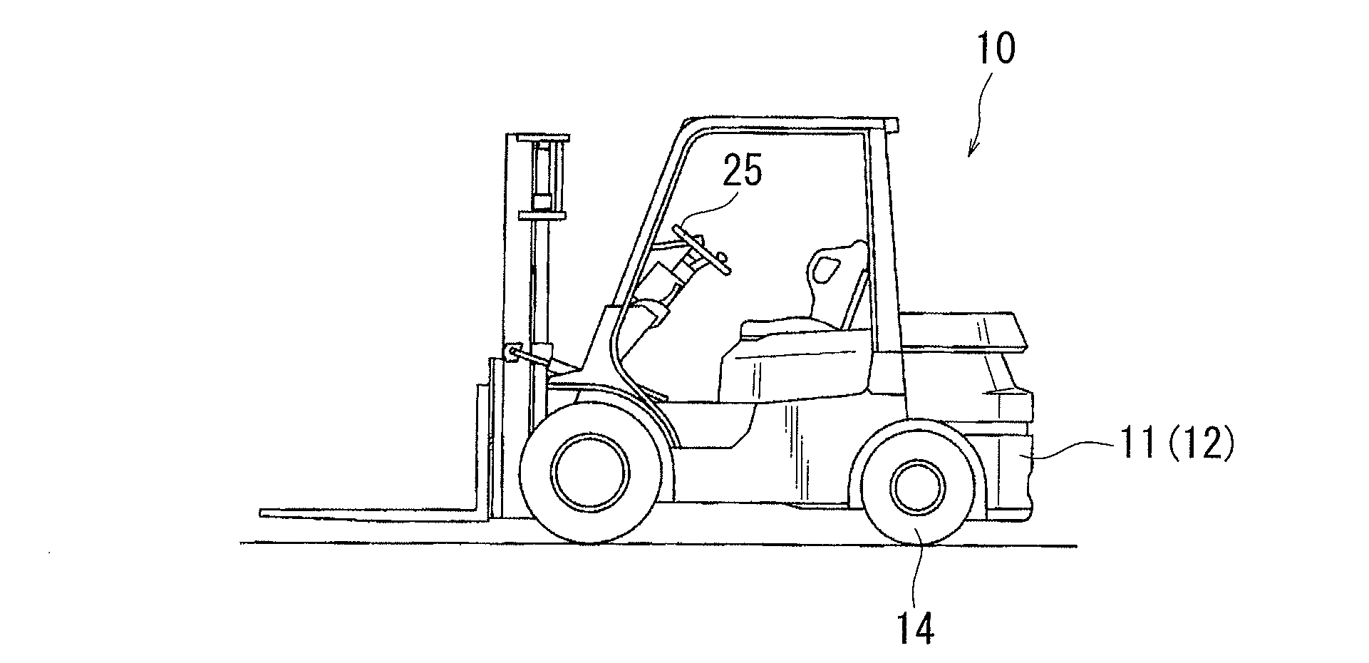
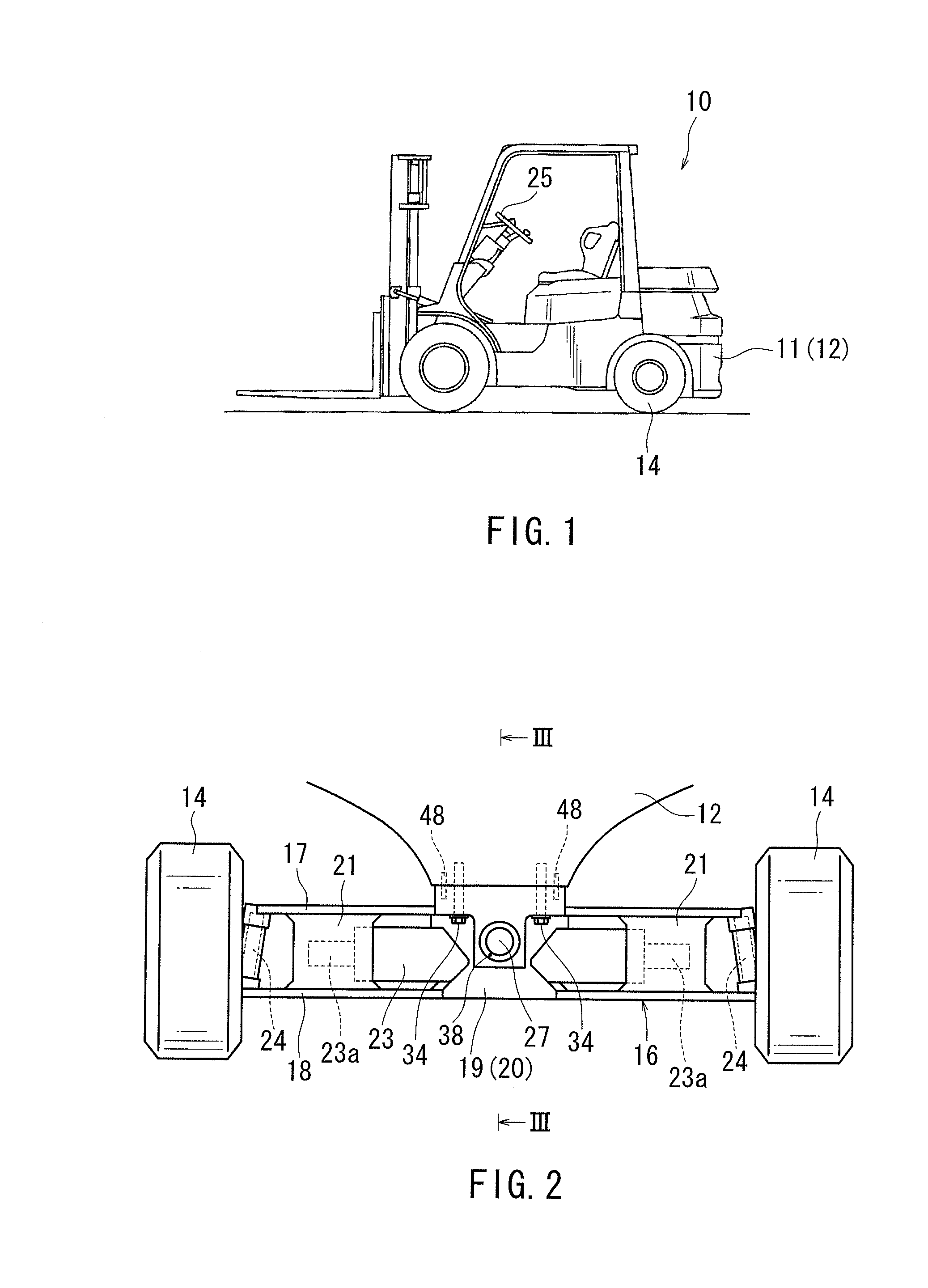
Embodiments of the present invention may include an axle support structure. The axle support structure has front and rear axle supports, an axle, and a bearing. The axle supports are provided on a vehicle body member of an industrial vehicle and have respectively a support hole. The axle is arranged between the front and rear axle supports, and has a pair of center pins. Each of the center pins is rotatably supported by the support hole. The bearing is inserted from an entrance of the support hole to be fit-engaged with the support hole. The bearing is provided between at least one of the center pins and a hole surface of the support hole corresponding to that center pin. At an end portion of the support hole opposite to the entrance, there is formed a stopper portion for preventing the bearing from passing through the support hole.

Description

[0001]This application claims priority to Japanese patent application serial number 2012-242738, the contents of which are incorporated herein by reference.BACKGROUND OF THE INVENTION[0002]1. Field of the Invention[0003]Embodiments of the present invention relate to axle support structures for industrial vehicles such as a forklift.[0004]2. Description of the Related Art[0005]A counterbalance type forklift has a machine base frame as a vehicle body member. The machine base frame is a rear frame of a machine frame. The machine base frame supports a rear axle so that the rear axle can swing within a roll plane. This helps to achieve an improvement in terms of a stability of the vehicle during traveling on a road surface that is not flat. FIG. 15 is a sectional view illustrating an industrial vehicle axle support structure.[0006]As shown in FIG. 15, a machine base frame 150 is provided with front and rear axle supports 151 and 152 arranged in the longitudinal direction (the horizontal ...

Claims


Application Information

Patent Timeline
IPC IPC(8): B60G1/00
CPCB60B35/18B60B35/02B60G9/02B60G2200/322B60G2204/15B60G2206/60B60G2300/022B60Y2200/15
Inventor WADA, KENICHIMOCHIZUKI, AKIRA
Owner TOYOTA IND CORP
Why Eureka
Try Eureka