Charger calibration device and charger calibration method

A technology of a calibration device and a calibration method, which is applied in the direction of circuit devices, battery circuit devices, current collectors, etc., can solve the problems of high manufacturing cost of chargers, inability to improve production capacity, high-quality rate and working hours, and low efficiency of charger calibration devices. Achieve the effect of reducing production man-hours, improving production capacity and good rate, and saving manufacturing costs

Inactive Publication Date: 2013-04-10
ALTEK CORP
View PDF3 Cites 7 Cited by
  • Summary
  • Abstract
  • Description
  • Claims
  • Application Information

AI Technical Summary

Problems solved by technology

[0008] In view of the above problems, the object of the present invention is to provide a charger calibration device and its calibration method to solve the problem of low efficiency of the charger calibration device, high manufacturing cost of the charger, and problems in the manufacturing process of electronic products such as cameras. Its production capacity, excellent rate and working hours cannot be improved.

Method used


Image

  • Charger calibration device and charger calibration method
  • Charger calibration device and charger calibration method
  • Charger calibration device and charger calibration method

Examples


Embodiment Construction

[0034] Hereinafter, embodiments of the charger calibration device and calibration method according to the present invention will be described with reference to related drawings. For ease of understanding, the same components in the following embodiments are described with the same symbols.

[0035] The charger calibration device and the calibration method of the present invention can be applied to various electronic devices such as digital cameras and digital cameras. In order to facilitate a better understanding of the technical features of the present invention, the following uses a digital camera as an example, but not as an example. limit.

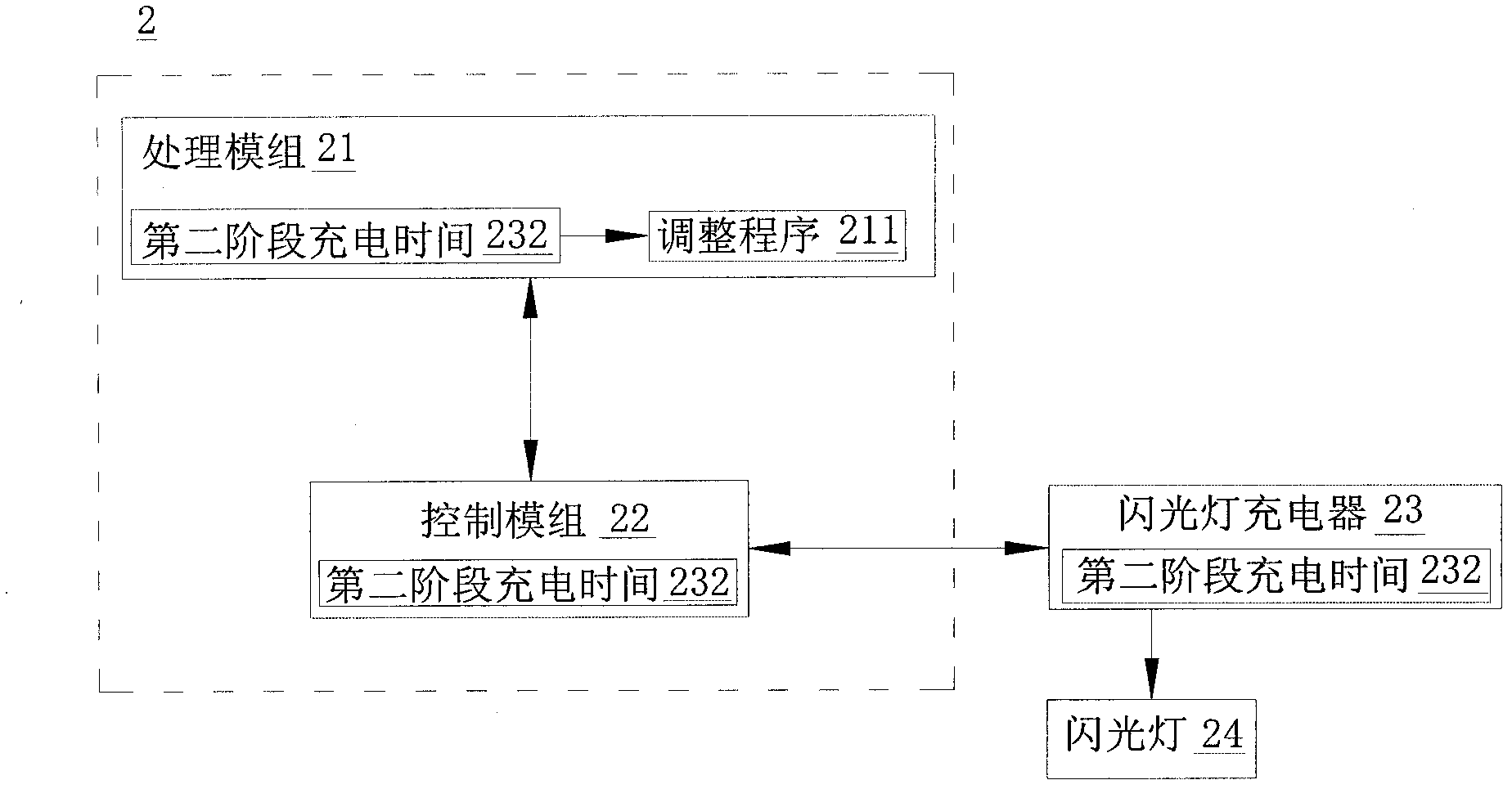
[0036] figure 2 It is a block diagram of the first embodiment of the charger calibration device of the present invention. As shown in the figure, the flash charger calibration device 2 of the present invention includes a processing module 21 and a control module 22. First, the processing module 21 will perform initial condition setting. A...


PUM


Abstract

The invention discloses a charger calibration device and a charger calibration method. The charger calibration device comprises a control module and a processing module. The control module controls a charger needed to be calibrated to carry out a first stage charging and a second stage charging to an electrical device. The processing module carries out a adjustment process according to the second stage charging time, so that high level quasi-periodicity of a pulse width modulating signal in a charging circuit of the charger need to be calibrated is adjusted. A preset high level quasi-periodicity is added or subtracted a preset adjustment range by the adjustment process, so that an updated high level quasi-periodicity is generated, then the preset adjustment range is reduced by half to generate an updated adjustment range, a calibration loop is repeated to preset times, and a calibration procedure is terminated.

Description

Technical field [0001] The present invention relates to a charger correction device, in particular to a lower cost and more efficient full-digit flash charger correction device and a correction method thereof. Background technique [0002] In digital cameras and digital cameras, the flash module is an indispensable component. In order to trigger the inert gas in the flash tube to shoot the flash, the flash circuit needs a charging capacitor to store energy. The charging voltage of this capacitor may be as high as 300 volts or more. Therefore, in order to be able to increase the capacitor voltage to a high voltage above 300 volts, a charging circuit is required in the flash lamp circuit to convert the energy of the battery into the capacitor. [0003] In the camera production process, in order to make all the produced cameras meet a specific technical specification, an upper limit is set for the flash charging time, so that each camera can have a similar charging time under the sam...

Claims


Application Information

Patent Timeline
IPC IPC(8): H02J7/00
Inventor 罗伟君陈培炘陈岳彰蔡昭宗
Owner ALTEK CORP
Why Eureka
Try Eureka