Method and System for Dianostic Measurement of Motor Vehicle Restraint System Squib Loop Resistance

a technology of dianostic measurement and squib loop, which is applied in the direction of instruments, pedestrian/occupant safety arrangements, vehicular safety arrangements, etc., can solve the problem of limited diagnostic capability and current solutions limited to trading efficient wiring methods

Active Publication Date: 2014-05-29
VEONEER US LLC
View PDF5 Cites 8 Cited by
  • Summary
  • Abstract
  • Description
  • Claims
  • Application Information

AI Technical Summary

Problems solved by technology

Current solutions are limited to trading efficient

Method used


Image

  • Method and System for Dianostic Measurement of Motor Vehicle Restraint System Squib Loop Resistance
  • Method and System for Dianostic Measurement of Motor Vehicle Restraint System Squib Loop Resistance
  • Method and System for Dianostic Measurement of Motor Vehicle Restraint System Squib Loop Resistance

Examples


Embodiment Construction

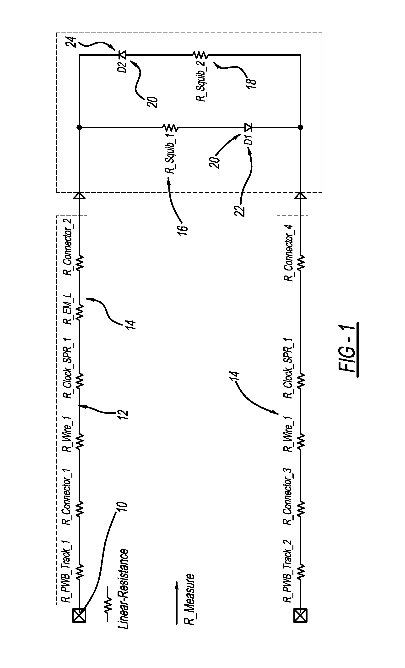
[0014]Referring to FIG. 1, a circuit schematic of a representative squib loop including non-linear components is illustrated. The control unit terminals 10 conduct a bias current through the conducting wire 12 and the linear resistance elements 14 of the squib loop. The linear resistance elements 14 include wire, connectors, clock-springs, EMI inductors and the individual squibs. Depending on the direction of the current bias, the current will flow through either the first squib 16 or the second squib 18. During diagnostic operation, the current is insufficient to initiate airbag inflation. The non-linear resistance elements 20 are illustrated here as the first diode 22 and second diode 24. The benefit of the diode placement in the design is more clearly represented by a simplified circuit schematic.

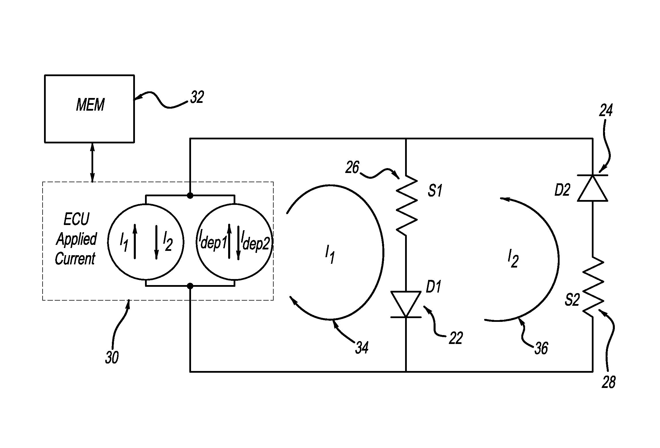
[0015]FIG. 2 represents a simplified circuit schematic with the individual linear resistance elements 14 combined into a first equivalent linear resistance 26, and a second equivalent li...


PUM


Abstract

A method of measuring squib loop resistance including non-linear elements in a restraint control module is disclosed by the present invention. The squib loop resistance is comprised of both linear and non-linear elements. The non-linear elements are linearized into resistive components about the bias points used to make the squib loop resistance measurement. The calculation of the linear squib loop resistance is provided by comparing the complete squib loop resistance and the linearized value of the non-linear elements.

Description

FIELD OF THE INVENTION[0001]The present invention relates generally to circuits used to measure resistance, and more particularly to a method and system for diagnostic measurement of squib loop resistance in a duplex of a motor vehicle airbag, occupant restraint system.BACKGROUND OF THE INVENTION[0002]Safety standards for modern automotive vehicles are becoming increasingly strict. The result of heightened standards and innovations by designers of vehicle resistant systems is twofold: 1) occupants of vehicles are safer and less likely to suffer serious injury in a collision, and 2) manufacturers are held to higher standards with little opportunity to offset costs. As a result of these trends, innovations that increase safety while retaining efficiency and low production costs are essential to manufacturers of related technology.[0003]Airbag systems typically are composed of a restraint control module and a reaction canister. The reaction canister contains a folded airbag and an infl...

Claims


Application Information

Patent Timeline
IPC IPC(8): B60R21/017
CPCB60R21/0173B60R21/017G01R27/14G01R31/006
Inventor EISWERTH, DAVIDCOLAROSSI, VINCENTKOCH, STUART ANDREW
Owner VEONEER US LLC
Why Eureka
Try Eureka