Projection display and method for displaying an overall image for projection free-form surfaces or tilted projection surfaces

a projection surface and projection display technology, applied in the direction of slide projectors, color television details, instruments, etc., can solve the problems of only being able to miniaturize known projection systems in a limited manner, the installation length of the system also increases to the same extent, and the luminosity loss of the projected imag

Active Publication Date: 2014-05-29
FRAUNHOFER GESELLSCHAFT ZUR FOERDERUNG DER ANGEWANDTEN FORSCHUNG EV
View PDF4 Cites 34 Cited by
  • Summary
  • Abstract
  • Description
  • Claims
  • Application Information

AI Technical Summary

Benefits of technology

[0019]In further embodiments of the present invention, the downstream overall lens can be implemented as optics having a variable focal length, so that an average projection distance can be adjusted.

Problems solved by technology

However, if the dimensions of the systems known in conventional technology are reduced for realizing miniaturized pico projectors, luminosity losses of the projected image result.
Miniaturization of known projection systems is only possible in a limited manner due to the limitation of the transmissible light flux through the small surface of the imaging system existing in these systems.
It is a general problem in single-channel projection systems that due to optical laws (e.g. natural vignetting, mapping errors), together with this surface to be mapped, the system installation length also increases to the same extent, which makes miniaturization more difficult.
However, problems occur when the above systems are used in connection with curved or tilted projection surfaces.
Generally, the problem is the front projection of an image across greatly changing projection distances or tilted, curved surfaces, and free-form screen geometries while ensuring high contrast and sharp mapping.
However, this known approach fails for curved projection surfaces.
Tilting again increases the necessitated installation space.
If even adaptivity to different degrees of tilting is to be realized, this necessitates mechanics for realizing the tilting between imaging structure and projection optics, which opposes the desired miniaturization and low production costs as well as robust construction.
An increased f-number could solve the problem by increasing the depth of focus, but such an increased f-number is also accompanied by lower light intensity causing other problems and additionally also opposing miniaturization, since the problem would then be shifted to the light source.
This does not increase installation height and apparatus effort.

Method used


Image

  • Projection display and method for displaying an overall image for projection free-form surfaces or tilted projection surfaces
  • Projection display and method for displaying an overall image for projection free-form surfaces or tilted projection surfaces
  • Projection display and method for displaying an overall image for projection free-form surfaces or tilted projection surfaces

Examples


Embodiment Construction

[0039]Before the present invention will be discussed in more detail below based on the figures, it should be noted that in the subsequently illustrated embodiments the same or functionally equal elements in the figures are provided with the same reference numbers. Thus, a description of elements having the same reference numbers can be interchanged and / or applied to different embodiments.

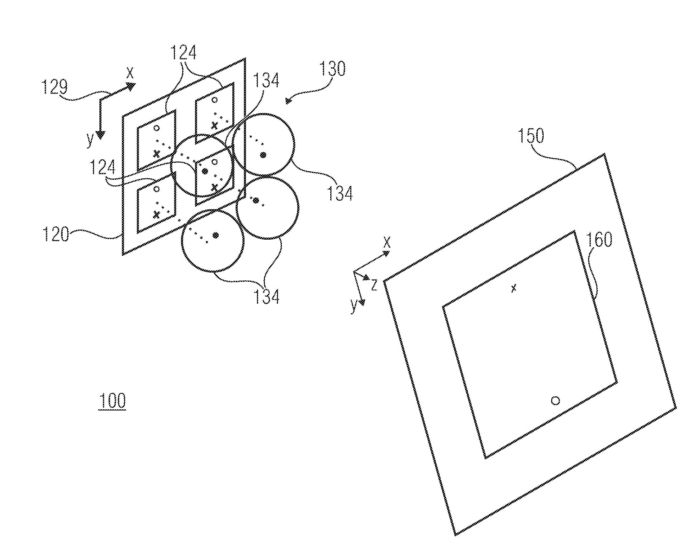
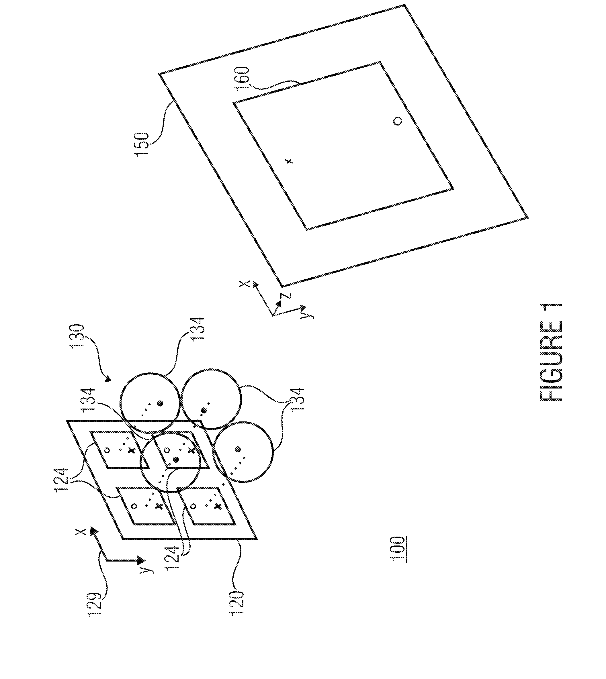
[0040]FIG. 1 shows a projection display 100 according to an embodiment of the present invention. The projection display 100 comprises an imaging system 120 and multi-channel optics 130. The imaging system 120 is implemented to generate or display individual images in a distribution of sub-areas 124 of an imaging plane 129 of the imaging system 120. The multi-channel optics 130 is configured to map one allocated sub-area 124 of the imaging system 120 each per channel, such that the mapping of the individual images is partly superimposed to an overall image 160 in a projection surface 150.

[0041]In FIG...


PUM


Abstract

A projection display with an imaging system is described, which is implemented to generate individual images in a distribution, such as a two-dimensional distribution, of sub-areas of an imaging plane of the imaging system, and a multi-channel optics that is configured to map one allocated individual image or one allocated sub-area of the imaging system each per channel, such that the mapping of the individual images is at least partly superimposed to an overall image in a projection surface, wherein the projection surface is a non-planar free-form surface, such as a curved surface, and / or tilted with respect to the imaging plane, and the imaging system is implemented such that constellations of points in the sub-images, each superimposed in a respective common point in the overall image by the multi-channel optics, differ depending on what distance the respective common point in the overall image has to the multi-channel optics.

Description

CROSS-REFERENCE TO RELATED APPLICATIONS[0001]This application is a continuation of copending International Application No. PCT / EP2012 / 058669, filed May 10, 2012, which is incorporated herein by reference in its entirety, and additionally claims priority from German Application No. 102011076083.0, filed May 18, 2011, which is also incorporated herein by reference in its entirety.BACKGROUND OF THE INVENTION[0002]Embodiments of the invention relate to a projection display and a method for displaying an overall image.[0003]The projection of dynamic image contents on a screen or as a virtual image with a digital liquid crystal-based imaging system is based, according to conventional technology, on projection devices having a mapping optical channel or three channels whose optical paths unite in front of the projection optics for realizing color mixing.[0004]In particular, US 2009 323 028 A1 shows pico projectors illuminated by LED in a color sequential manner. Further, US 2009 237 616 A1...

Claims


Application Information

Patent Timeline
Patent Type & Authority Applications(United States)
IPC IPC(8): G03B21/14
CPCG03B21/001G03B21/005G03B21/147H04N9/3147H04N9/3185H04N9/3197G03B21/142
Inventor SIELER, MARCELSCHREIBER, PETER
Owner FRAUNHOFER GESELLSCHAFT ZUR FOERDERUNG DER ANGEWANDTEN FORSCHUNG EV
Why Eureka
Try Eureka