Bale handling

Inactive Publication Date: 2014-05-29
ANDERSON PAUL JAMES +1
View PDF9 Cites 3 Cited by
  • Summary
  • Abstract
  • Description
  • Claims
  • Application Information

AI Technical Summary

Benefits of technology

[0048]In preferred embodiments the holding portion may include rounded corners and an avoidance of sharp projections so as

Problems solved by technology

This method becomes particularly inefficient if a small number of bales are required to be transported a short distance.
The disadvantage of this approach is often the lifting apparatus is not designed for transportation of the bales over any significant distance.
This is a disadvantage if a number of bales need to be moved

Method used


Image

  • Bale handling
  • Bale handling
  • Bale handling

Examples


Embodiment Construction

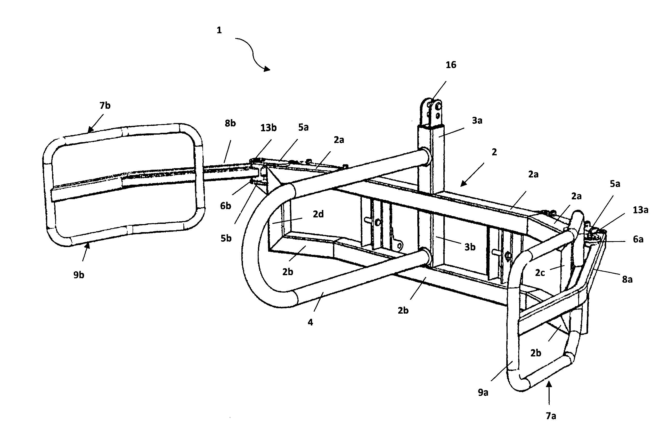
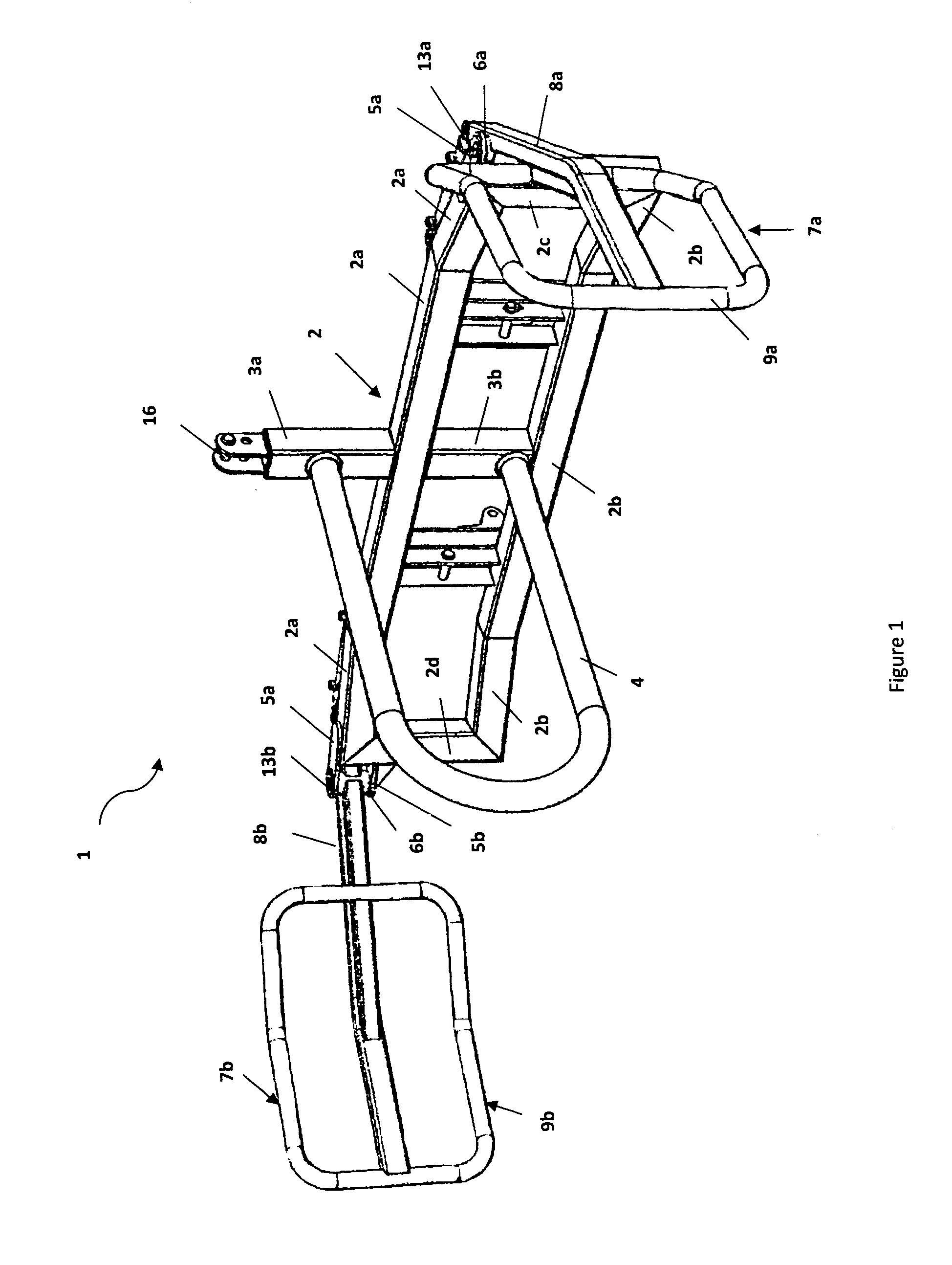
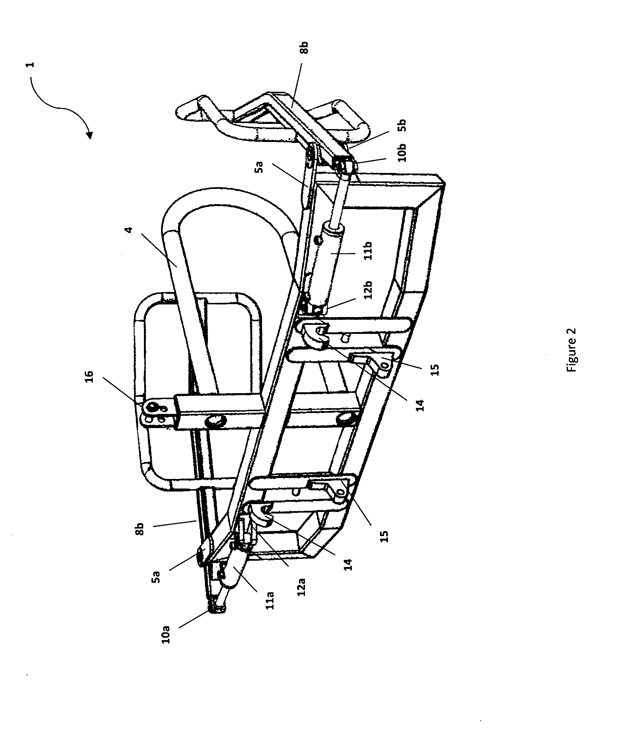
[0068]With respect to FIG. 1, there is shown a bale grab device in an open configuration, as generally indicated by arrow 1.

[0069]The bale grab device 1 has frame member 2 which comprises upper members 2a, lower frame members 2b, left frame member 2c and right frame member 2d, together which form an approximate partially curved frame member of the bale grab device. The curvature attained generally corresponds to the diameter of a standard round bale (not shown), although both larger and smaller bales can be gripped. The flat front face 17 provides a further region onto which a square bale (not shown) can be gripped. Attached to frame member 2 by brace member 3a, and tilt arm 3b is a central projecting member in the form of a U-shaped tube 4. The central projecting member 3b is attached orthogonally to the centre of the front face 17 of frame member 2. Welded to the upper ends of left 2c and right 2d frame members are upper 5a and lower 5b hinge plates. Left grab arm 7a pivot bushing...


PUM


Abstract

A bale grab device is provided which includes: at least one frame member; a central projecting member; and at least two holding arms, wherein the holding arms are located on either side of the central projecting member and wherein each holding arm is configured to be capable of being independently moved between an open and a closed position wherein a separate gripping region is provided between each of the holding arms and the central projecting member.

Description

TECHNICAL FIELD [0001]The present invention relates to improvements in and relating to bale handling. In particular, the present invention relates to bale handling apparatus for lifting and transporting bales.BACKGROUND ART [0002]Apparatus for lifting and transporting hay bales are well known in the art. Typically two different types of handling equipment are used for transporting bales, the first is used for lifting bales and locating them on the second type of handling equipment, namely the transporting apparatus.[0003]This method becomes particularly inefficient if a small number of bales are required to be transported a short distance. The only other option being to transport the bales using only the first lifting apparatus. The disadvantage of this approach is often the lifting apparatus is not designed for transportation of the bales over any significant distance. The known prior art lifting apparatus are typically only designed to lift and place one bale at a time. This is a ...

Claims


Application Information

Patent Timeline
IPC IPC(8): A01D87/12
CPCA01D87/127
Inventor ANDERSON, PAUL JAMESANDERSON, MICHELLE STEPHANIE
Owner ANDERSON PAUL JAMES
Why Eureka
Try Eureka