Virtual ccap cable modem termination system with software reconfiguable mac and phy capability

Active Publication Date: 2014-05-29
VECIMA NETWORKS
View PDF3 Cites 27 Cited by
  • Summary
  • Abstract
  • Description
  • Claims
  • Application Information

AI Technical Summary

Benefits of technology

[0051]One advantage of the invention's CMRTS units is that because they can be designed to be highly software configurable, and additionally to have software configurable hardware as well due to FPGA and DSP based MAC and PHY components, the same CMRTS units can be reconfigured to work with the first backwards compatible CMRT option, the second more radical CMTS option (design), or a wide variety of other options, such as the previously discussed virtual CCAP system as well. Because the CMRTS design is both software configurable and in some configurations can (but need not) allow for the pass through of prior art CATV RF to optical signals, the CMRTS can be configured to be also highly backward compatible as needed, and can be implemented in a way that can be largely transparent to the cable operator until the higher functionality of the CMRTS is required.
[0052]In some embodiments, the first communications media, used to transmit legacy CATV data over the optical fiber, may handle a substantial part of the data that is ultimately delivered to and from the various sections of neighborhood cable. In other embodiments, the first communications media may handle no legacy CATV data whatsoever, and all data that is ultimately delivered to and from the various sections of neighborhood cable will travel through the second communications media. In these later embodiments, there essentially may be no first communications media. Nonetheless, because the present invention enables both possibilities, it is useful to retain the nomenclature of a first communications media that is used to transmit legacy CATV signals over optical fiber, and a second communications media, which may physically be identical with the first communications media, that is used to transmit Ethernet data packets/frames and the like that will require either decoding and reformatting at the CMRTS units, or else remodulation at the CMRTS units, in order to transfer information between the optical and cable portions of the HFC system.
[0053]For either the first or second option, the second communications media used to transmit data to the CMRTS may optionally use a second optical fiber and an alternative data transmission protocol, such as various Ethernet protocols previously discussed. If this scheme was used, the data would require conversion, reformatting, and QAM modulation by the remote CMRTS units. Here, for example, the FPGA and DSP units in the CMRTS units could be configured as QAM modulators that would then provide a radiofrequency (RF) QAM signal that can be injected into the cable, and recognized by cable modems attached to the various cables. In this configuration, to avoid conflicts, if any data is being transmitted over the first communications media, then to avoid interference, it may be useful to have the frequency (or at least time slice) of the QAM waveforms provided by the CMRTS units differ from the frequency (or at least time slice) of any Q

Problems solved by technology

Unfortunately, even in a coax cable, there is a finite amount of bandwidth available to transmit data.
Coax cables and their associated radiofrequency interface equipment have typically only used the frequency range under about 1000 MHz, and so there are limits to how much data the 1950's era coaxial cable can ultimately transmit.
Although ideally, the best way to satisfy the ever increasing household demand for digital data (e.g. video—on demand, high speed Internet, voice over IP, etc.) would be by extending optical fiber to each household, this would be an incredibly expensive solution.
It is impractical to directly connect each individual neighborhood CATV cable directly to the cable head.
However it is also impractical to run individual f

Method used


Image

  • Virtual ccap cable modem termination system with software reconfiguable mac and phy capability
  • Virtual ccap cable modem termination system with software reconfiguable mac and phy capability
  • Virtual ccap cable modem termination system with software reconfiguable mac and phy capability

Examples


Embodiment Construction

[0099]In one embodiment, the invention may be a distributed Cable Modem Termination System (CMTS) for a Hybrid Fiber Cable (HFC) network. This system will typically consist of multiple parts.

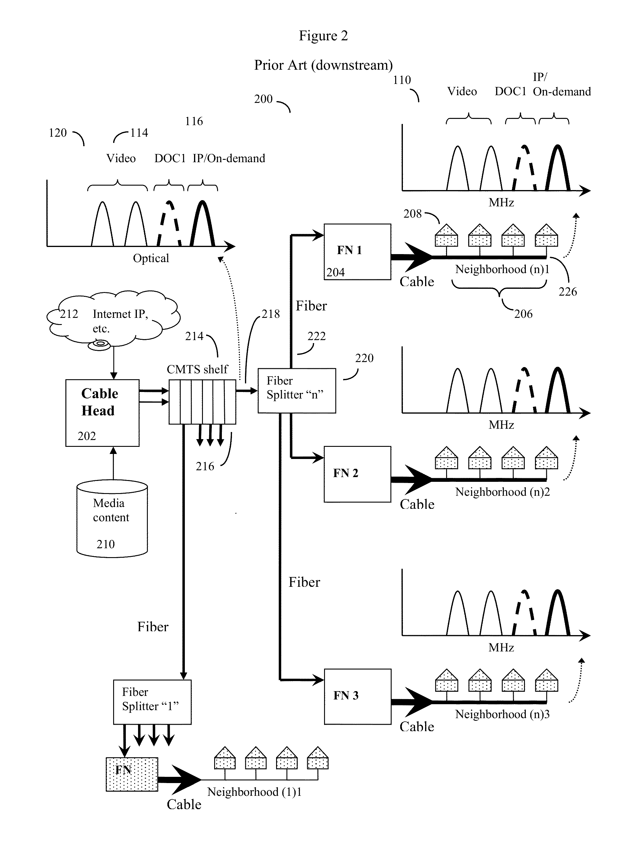
[0100]In some embodiments, the system will work essentially independently of the CMTS at the cable head, and will essentially act to supplement the functionality of prior art cable heads and CMTS by adding a minimal amount of new equipment at the cable head. Here, this new equipment at the cable head cable may mainly consist of a Level 2 / 3 switch, a virtual shelf management system (to be described), and appropriate MAC and PHY devices to send and receive data along optical fibers. The prior art cable head CMTS may continue to operate as before, with the one exception that the cable operator should provide for at least some empty cable channels in order to provide space for the new channels provided by the invention.

[0101]In some embodiments, however, the prior art cable head and CMTS may be repl...


PUM


Abstract

Distributed and software reconfigurable remote CMTS (CMRTS) device, based on MAC and PHY units with FPGA and DSP components, for a HFC CATV network. The various CATV RF modulators, such as QAM modulators, may be located entirely at the fiber nodes if desired. Although a basic set of CATV QAM data waveforms may optionally be transmitted to the nodes using a first fiber, in a preferred embodiment, all data may be transmitted to the nodes using other protocols such as Ethernet protocols. The nodes will extract the data specific to each neighborhood and inject this data into the cable portion of the system as RF waveforms, such as RF QAM channels. A computerized “virtual shelf” control system for managing and reconfiguring the FPGA and DSP based CMTRS units, as well as a new type of edge router based all-digital virtual head end (virtual converged cable access platform) is also disclosed.

Description

CROSS REFERENCE TO RELATED APPLICATIONS[0001]This application is a continuation in part of U.S. patent application Ser. No. 13 / 555,170 “DISTRIBUTED CABLE MODEM TERMINATION SYSTEM WITH SOFTWARE RECONFIGURABLE MAC AND PHY CAPABILITY”, inventor Shlomo Selim Rakib, filed Jul. 22, 2012; and application Ser. No. 13 / 555,170 is also a continuation in part of U.S. patent application Ser. No. 13 / 035,993 “METHOD OF CATV CABLE SAME-FREQUENCY TIME DIVISION DUPLEX DATA TRANSMISSION”, inventor Shlomo Selim Rakib, filed Feb. 27, 2011, now U.S. Pat. No. 8,365,237; application 13 / 555,170 also claimed the priority benefit of U.S. provisional application 61 / 511,395 “IMPROVED HYBRID FIBER CABLE SYSTEM AND METHOD”, inventor Shlomo Selim Rakib, filed Jul. 25, 2011, now expired; This application is also a continuation in part of U.S. patent application Ser. No. 14 / 098,656 “VIRTUAL CONVERGED CABLE ACCESS PLATFORMS FOR HFC CABLE NETWORKS”, filed Dec. 6, 2013; application Ser. No. 14 / 098,656 in turn was a con...

Claims


Application Information

Patent Timeline
IPC IPC(8): H04N21/61
CPCH04N21/6118H04N21/2383H04N21/478H04N21/4782H04N21/4786
Inventor RAKIB, SHLOMO SELIM
Owner VECIMA NETWORKS
Why Eureka
Try Eureka