Tire air pressure transmission device and tire air pressure monitoring system
- Summary
- Abstract
- Description
- Claims
- Application Information
AI Technical Summary
Benefits of technology
Problems solved by technology
Method used
Image
Examples
Embodiment Construction
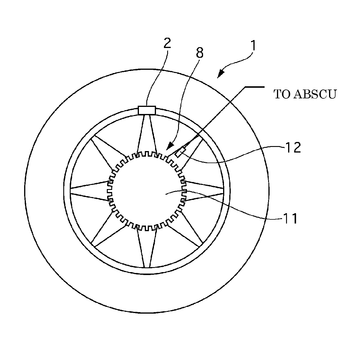
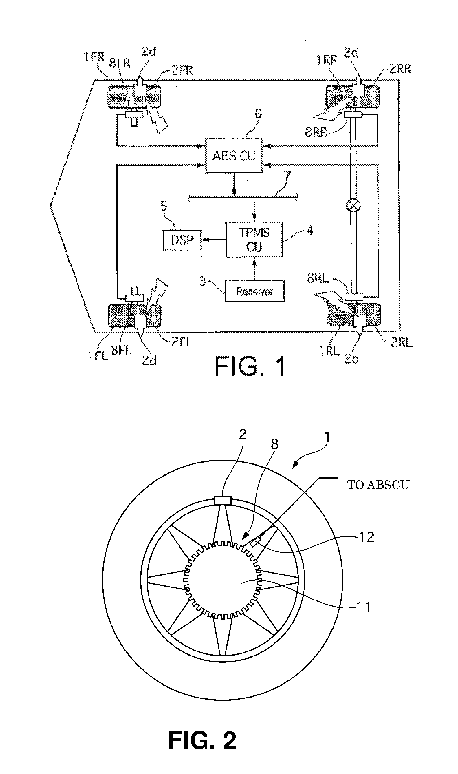
[0024]FIG. 1 is a configuration diagram illustrating a tire air or pneumatic pressure monitoring system 13 in a first embodiment. In this figure, the end letters annexed to each reference sign is intended to indicate as follows: FL stands for the left front wheel, FR stands for the right front wheel, RL stands for the left rear wheel, and RR stands for the right rear wheel, respectively. In the following description, when not specifically necessary, the description of FL, FR, RL and RR will be omitted.
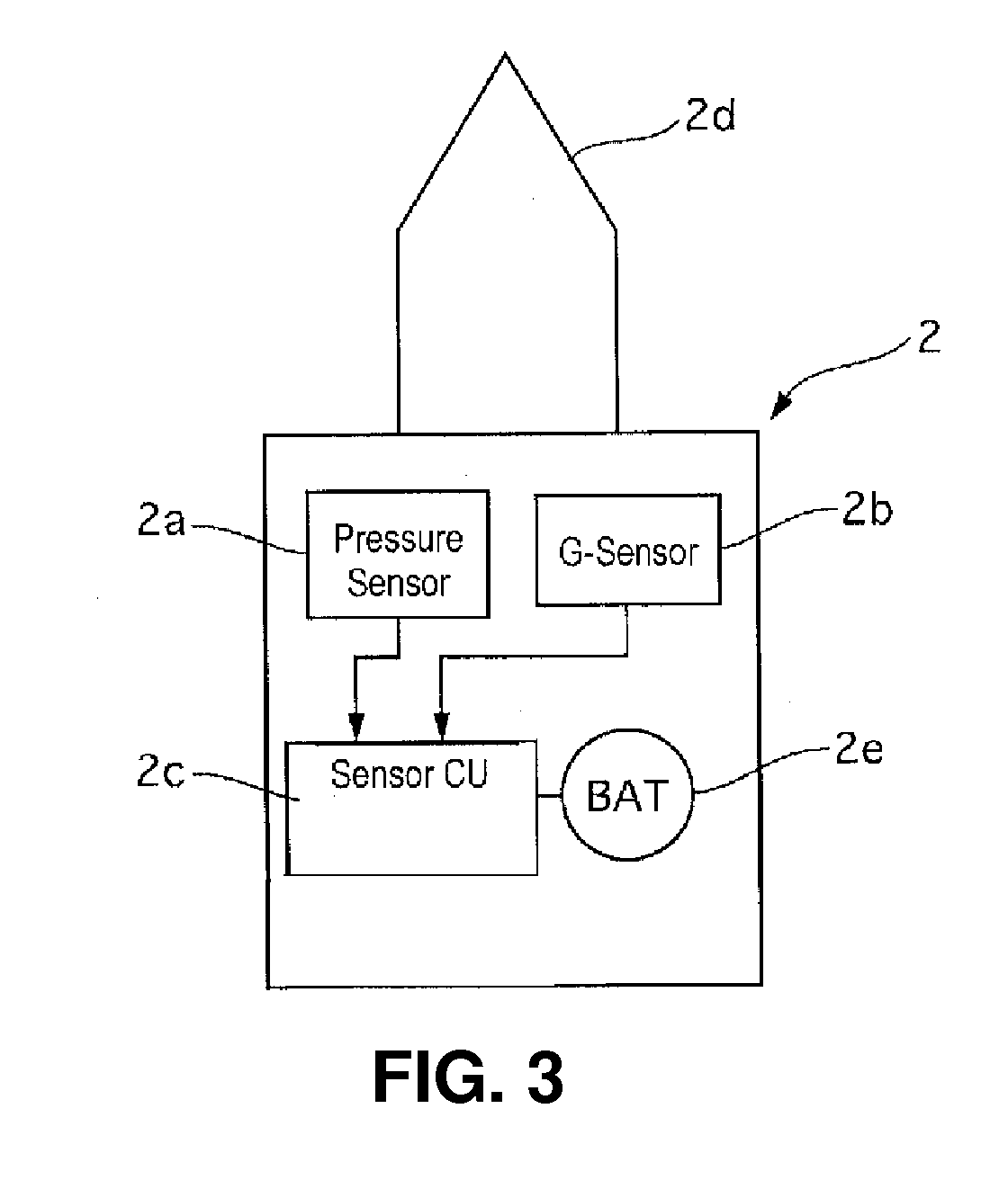
[0025]The tire air pressure monitoring device 13 in the first embodiment is provided with TPMS (Tire Pressure Monitoring System) sensors 2 and a TPMS main unit 14. The TPMS main unit 14 is provided with a receiver 3, a TPMS control unit 4, a display 5, and an ABS (Antilock Brake System) control unit 6, and a wheel speed sensors 8.
[0026]FIG. 2 shows a wheel 1. As shown in FIG. 2, the TPMS sensor 2 is installed on each of the wheels 1 at an air valve position near the outer circumferenti...
PUM
 Abstract
Description
Claims
Application Information
 - Generate Ideas
- Intellectual Property
- Life Sciences
- Materials
- Tech Scout
- Unparalleled Data Quality
- Higher Quality Content
- 60% Fewer Hallucinations
Browse by: Latest US Patents, China's latest patents, Technical Efficacy Thesaurus, Application Domain, Technology Topic, Popular Technical Reports.
© 2025 PatSnap. All rights reserved.Legal|Privacy policy|Modern Slavery Act Transparency Statement|Sitemap|About US| Contact US: help@patsnap.com


