
Modeling apparatus and operation method thereof

a modeling apparatus and model technology, applied in the field of modeling apparatus, can solve the problems of complicated structure of work pieces, drawbacks of dimensional constraints, and work pieces manufactured by conventional injection molding technology, and achieve the effects of high dimensionality, complicated structural design, and increased pressure of the first pushing mechanism

Active Publication Date: 2014-06-05
WISTRON CORP
View PDF10 Cites 2 Cited by
  • Summary
  • Abstract
  • Description
  • Claims
  • Application Information

AI Technical Summary

Benefits of technology

The present invention is a modeling apparatus that manufactures optical work pieces with high dimensional precision, optical properties, and complicated structural design. The apparatus includes a valve that does not inject plastic by high pressure, resulting in low injecting pressure and reducing the mold-locking force between the first and second sets of molds. The apparatus also improves the exhaust of gaseous matter during compression of the accommodating space, preventing stress residue and manufacturing work pieces without stress residue. The apparatus can manufacture work pieces with low tolerance and can apply in-mold decoration technology to transfer decoration ink onto the work piece. The apparatus can fill the plastic into the accommodating space quickly, even through it is sticky, allowing for effective modeling of thin-typed complicated structures such as computer casings, increasing manufacturing efficiency.

Problems solved by technology

The conventional injection molding technology can manufacture the work piece with complicated structure.
However, fluidity of the fluid plastic is worse, the work piece manufactured by the conventional injection molding technology has drawback of dimensional constraint.
The fluid plastic is injected from the valve by the high pressure, so that distribution of the fluid plastic is not uniform inside the modeling chamber, and the work piece may have fault of stress residue.
Hydraulic cylinder of the conventional injection compression molding technology only moves the core to manufacture the work piece with simple and smooth structure, which means the conventional injection compression molding technology can not manufacture the component with complicated structure.
In addition, the conventional injection molding technology and the conventional injection compression molding technology manufacture the product according to shape of the mold structure, and have no appearance decoration function.
Therefore, design of a modeling apparatus and an operation method capable of manufacturing the component with complicated structure and having function of appearance decoration is an important issue in the related industry.

Method used


Image

  • Modeling apparatus and operation method thereof
  • Modeling apparatus and operation method thereof
  • Modeling apparatus and operation method thereof

Examples


Embodiment Construction

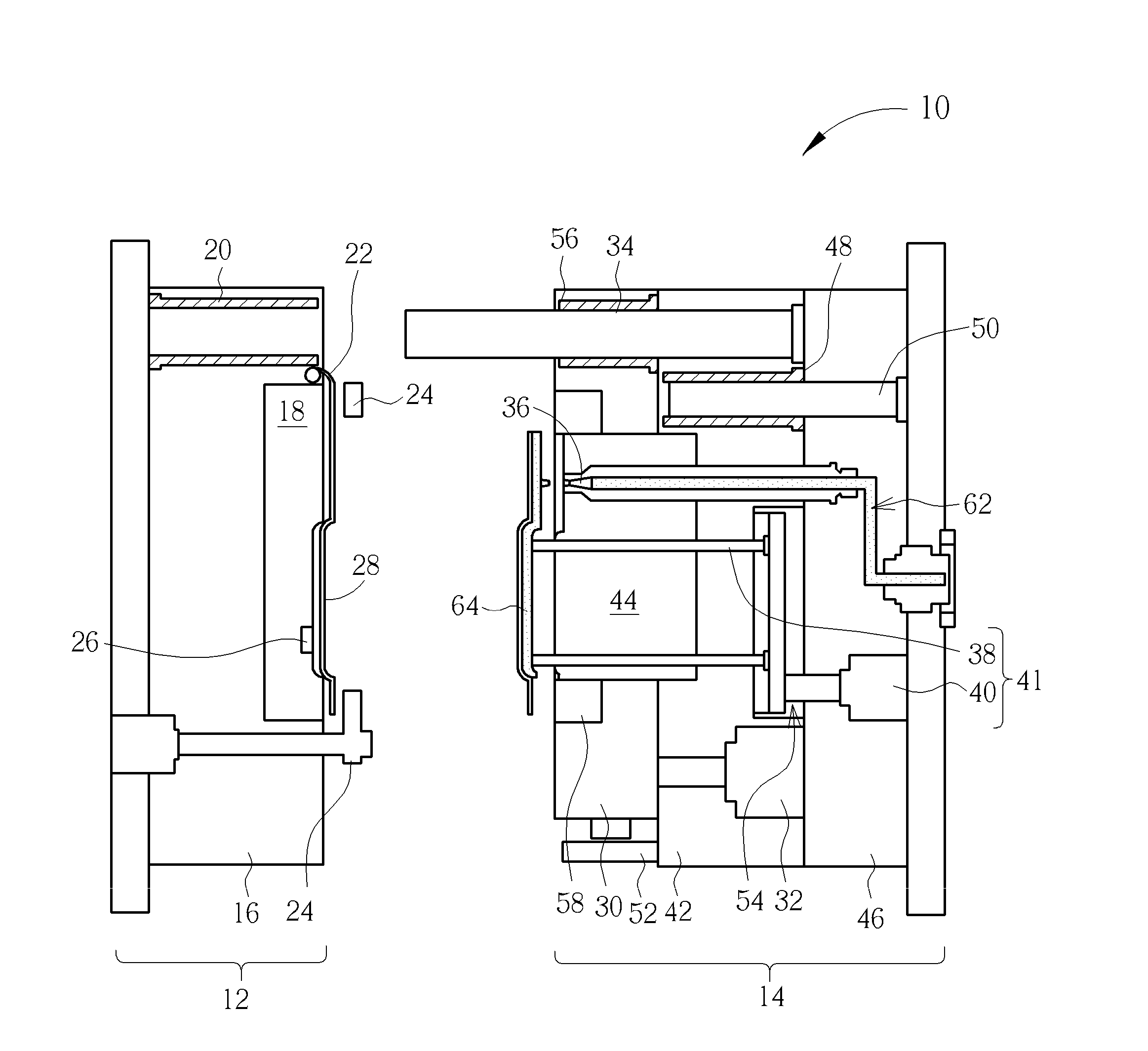
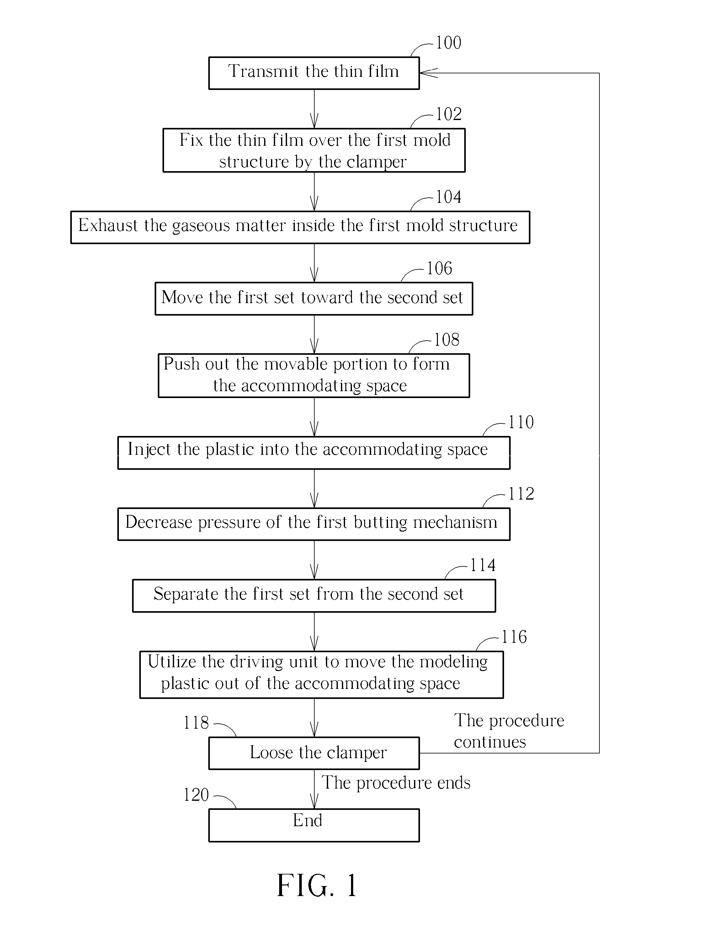
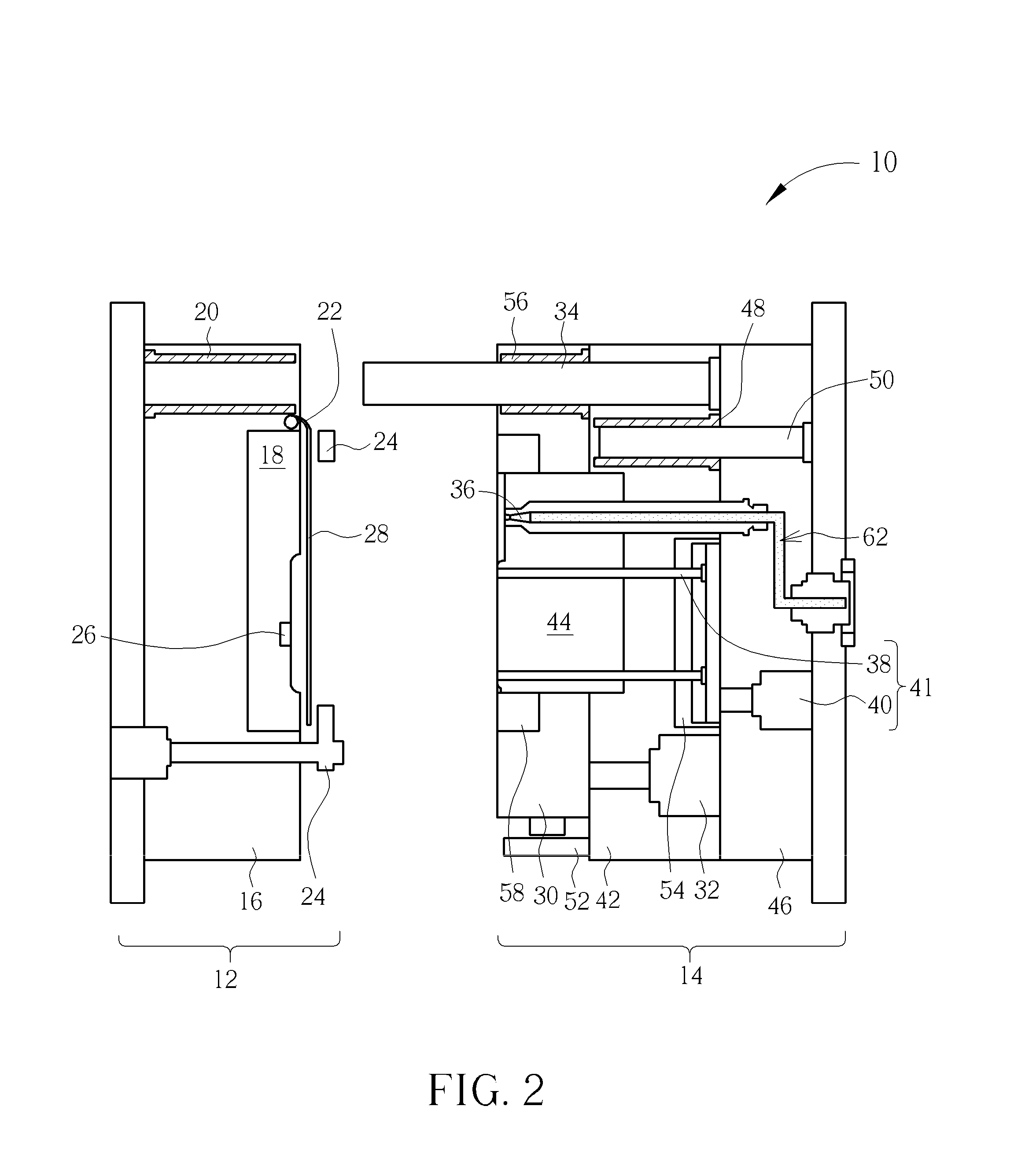
[0033]Please refer to FIG. 1 to FIG. 7. FIG. 1 is a flow char of an operation method of a modeling apparatus 10 according to an embodiment of the present invention. FIG. 2 to FIG. 7 respectively are diagrams of the modeling apparatus 10 in different modes according to the embodiment of the present invention. The modeling apparatus 10 includes a first set 12 and a second set 14. The first set 12 can be movably disposed on the second set 14 to manufacture plastic product. The first set 12 includes a body 16, a first mold structure 18 and a guiding slot 20. The first mold structure 18 can be a sunken space formed on a surface of the body 16 facing the second set 14. The guiding slot 20 is formed inside or by the body 16. The first set 12 further can include a conveyer 22, a clamper 24 and an extractor 26. The conveyer 22 is disposed on the body 16 to transmit a thin film 28 for covering the thin film 28 over the first mold structure 18.

[0034]The modeling apparatus 10 can include a plur...


PUM

PropertyMeasurementUnit
pressureaaaaaaaaaa
movement distanceaaaaaaaaaa
compressaaaaaaaaaa

Abstract

A modeling apparatus includes a first set and a second set. The first set includes a body and a first mold structure, the first mold structure is disposed on a surface of the body. The second mold includes a movable portion, a first pushing mechanism, a valve and a second pushing mechanism. A second mold structure of the movable portion is combined with the first mold structure to form an accommodating space. The first pushing mechanism is connected to the movable portion for moving the movable portion, so as to combine the second mold structure with the first mold structure. The valve is disposed on the second mold structure for injecting plastic into the accommodating space. The second pushing mechanism is connected to the pushing component. The second pushing mechanism drives the pushing component to pierce through the movable portion, to move the modeled plastic out of the accommodating space.

Description

BACKGROUND OF THE INVENTION[0001]1. Field of the Invention[0002]The present invention relates to a modeling apparatus, and more particularly, to a modeling apparatus and a related operation method capable of manufacturing a complicated structure which has no stress residue.[0003]2. Description of the Prior Art[0004]A conventional injection molding technology is utilized to manufacture a casing of the electronic device. By the conventional injection molding technology, fluid plastic is injected into a modeling chamber by high pressure, and the modeling chamber can be filled with the fluid plastic to model the fluid plastic. The modeling chamber includes two mold structures. The mold structures can be separate from each other, and a pushing mechanism is utilized to move the solid plastic (modeled from the fluid plastic) out of the modeling chamber. The conventional injection molding technology can manufacture the work piece with complicated structure. However, fluidity of the fluid pl...

Claims


Application Information

Patent Timeline
Patent Type & Authority Applications(United States)
IPC IPC(8): B29C45/14
CPCB29C45/14336B29C45/14778B29C45/14016B29C45/561
Inventor HUNG, CHUN-YENHSIAO, YA-CHI
Owner WISTRON CORP
Learn More