Brake System for Motor Vehicles. and Method for Operating the Brake System

a brake system and motor vehicle technology, applied in the direction of brake systems, fluid braking transmissions, vehicle components, etc., can solve the problem of large brake pedal force or brake pedal displacement that must be applied

Active Publication Date: 2014-06-05
CONTINENTAL TEVES AG & CO OHG
View PDF37 Cites 60 Cited by
  • Summary
  • Abstract
  • Description
  • Claims
  • Application Information

AI Technical Summary

Benefits of technology

[0008]One advantage of the invention lies in the fact that pressure and / or volume boosting of the brake pedal actuation which is applied by the vehicle driver can be carried out by means of the second pressure provision device.
[0009]According to one preferred embodiment of the brake system according to the invention, it includes an electrically operated adding valve per brake circuit for hydraulically connecting the first pressure provision device to the brake circuit. The adding valve is in each case arranged particularly preferably in a hydraulic connecting line between the first pressure provision device and the brake circuit or the brake circuit supply line and thus makes optional opening or closing of the hydraulic connection between the first pressure provision device and the brake circuit possible. The adding valves are particularly preferably of normally closed configuration, in order that the brake circuit is separated hydraulically from the first pressure provision device in a currentless fallback operating mode. It is preferred that an outlet connector of the separating valve and an outlet connector of the adding valve are connected hydraulically for each brake circuit. The hydraulic connection particularly preferably is placed in the brake circuit supply line.
[0010]The first electronic control and regulating unit is preferably configured for actuating the first electrically controllable pressure provision device in the sense of regulation or control of the hydraulic pressure which is output by it. Furthermore, the separating valves and adding valves and the simulator release valve of the brake system are advantageously regulated and / or controlled by the first control and regulating unit.
[0011]The brake system preferably includes an electrically operated, advantageously normally open, inlet valve and an electrically operated, advantageously normally closed, outlet valve per wheel brake for setting wheel-individual brake pressures. The inlet connectors of the inlet valves of the wheel brakes of a brake circuit are particularly preferably connected to a brake circuit supply line which is connected to an outlet connector of the separating valve which belongs to the brake circuit.
[0012]The inlet valves and outlet valves are preferably likewise actuated by the first electronic control and regulating unit.
[0013]The separating valve is in each case preferably arranged in a hydraulic connecting line between the pressure space and the brake circuit supply line and thus makes optional closing or opening of the hydraulic connection between the pressure space and the brake circuit supply line possible. The separating valves are particularly preferably of normally open configuration, in order that the brake circuits are connected hydraulically to the brake master cylinder in a currentless fallback operating mode and can thus be loaded with pressure by the vehicle driver.

Problems solved by technology

In the previously known brake system, it is considered to be disadvantageous that, if the actuation or the drive of the electrically controllable pressure provision device fails, great brake pedal forces or brake pedal displacements have to be applied by the driver, in order to achieve sufficient service brake deceleration.

Method used


Image

  • Brake System for Motor Vehicles. and Method for Operating the Brake System
  • Brake System for Motor Vehicles. and Method for Operating the Brake System
  • Brake System for Motor Vehicles. and Method for Operating the Brake System

Examples


Embodiment Construction

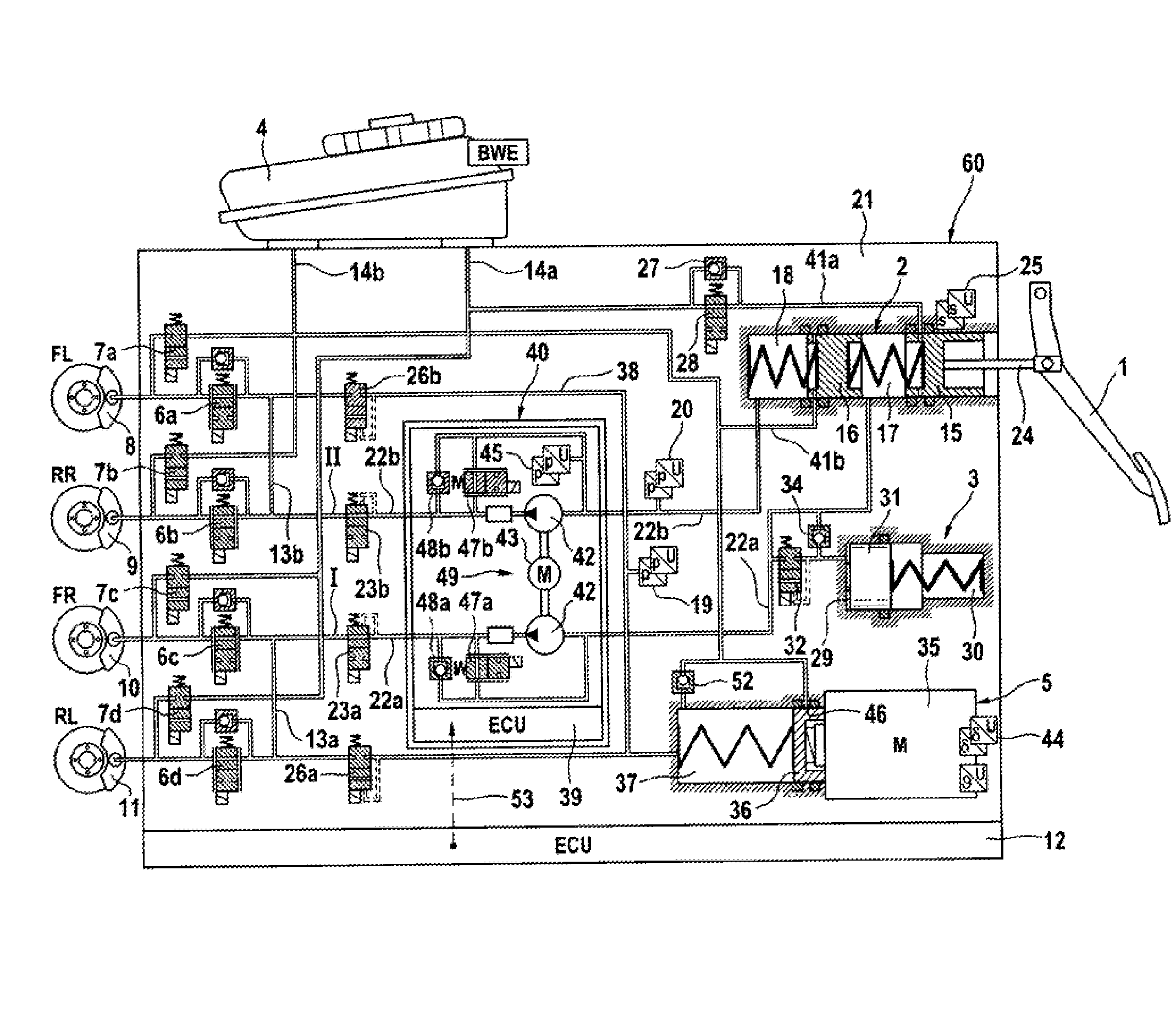
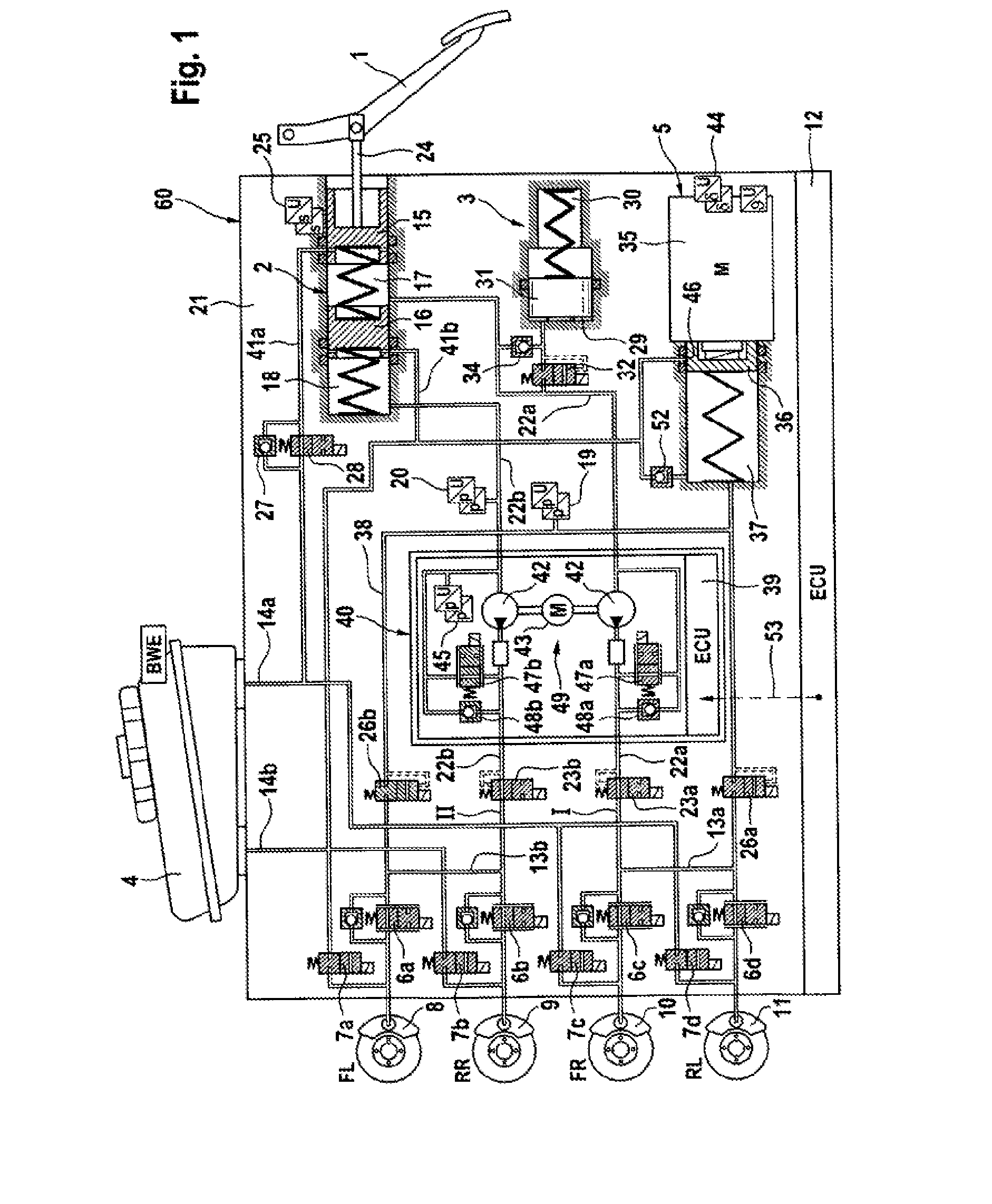
[0038]FIG. 1 diagrammatically shows a first exemplary embodiment of a brake system according to the invention. The brake system substantially includes a hydraulic actuating unit 2 which can be actuated by means of an actuating or brake pedal 1, a displacement simulator or simulation device 3 which interacts with the hydraulic actuating unit 2, a pressure medium storage vessel 4 which is under atmospheric pressure and is assigned to the hydraulic actuating unit 2, a first electrically controllable pressure provision device 5, a second electrically controllable pressure provision device 49, an electronic control and regulating unit 12 and an electrically controllable pressure modulation device.

[0039]According to the example, the pressure modulation device includes, per wheel brake 8, 9, 10, 11 of a motor vehicle (not shown), an inlet valve 6a-6d and an outlet valve 7a-7d which are connected together hydraulically in pairs via central connectors and to which wheel brakes 8, 9, 10, 11 a...


PUM


Abstract

A motor vehicle brake system actuated in brake-by-wire and fallback operating modes, having a brake master cylinder, brake circuits, a pressure medium storage vessel, a brake pedal, a separating valve for separating the brake circuit into a first section connected to the separating valve the master cylinder, and a second section connected to the separating valve and the wheel brakes. A first pressure provision device has a piston actuated by an actuator, a simulation device connected by a simulator release valve to the master cylinder for a pleasant brake pedal feel in the brake-by-wire operating mode. A first electronic control and regulating unit actuates the first pressure provision device, the separating valves and the simulator release valve. A second pressure provision device has a suction connector and a pressure connector per brake circuit being connected to the inlet of the separating valve.

Description

CROSS REFERENCE TO RELATED APPLICATIONS[0001]This application claims priority to German Patent Application Nos. 10 2011 075 325.7, filed May 5, 2011, 10 2011 075 330.3, filed May 5, 2011, 10 2011 075 331.1, filed on May 5, 2011, 10 2012 205 962.8, filed on Apr. 12, 2012, and PCT / EP2012 / 056894, filed Apr. 16, 2012.FIELD OF THE INVENTION[0002]The invention relates to a brake system for motor vehicles and to a method for operating a brake system of this type.BACKGROUND[0003]Hydraulic vehicle brake systems are known which are configured as power-assisted brake systems and, in addition to a brake master cylinder which can be actuated by muscular force, to which wheel brakes are connected hydraulically and which provides pressure and volume for actuating wheel brakes, include a further, electrically controllable pressure and volume provision device which actuates the wheel brakes in a “brake-by-wire” operating mode. If the electrically controllable pressure and volume provision device fai...

Claims


Application Information

Patent Timeline
Patent Type & Authority Applications(United States)
IPC IPC(8): B60T13/58B60T13/68B60T13/16
CPCB60T13/58B60T13/686B60T13/161B60T8/4081B60T8/441B60T13/66B60T13/588B60T13/142
Inventor BILLER, HARALDDRUMM, STEFAN A.BESIER, MARCOLINKENBACH, STEFENSCHARF, CHRISTOPHER
Owner CONTINENTAL TEVES AG & CO OHG
Why Eureka
Try Eureka