Hydraulic Brake Master Cylinder

a hydraulic brake and master cylinder technology, applied in the direction of fluid couplings, bicycle brakes, instruments, etc., can solve the problems of limiting the location of the gear shifter, the shape of the master cylinder is typically not adjustable, and the current adjuster is difficult to us

Inactive Publication Date: 2008-07-03
HAYES BICYCLE GROUP
View PDF111 Cites 42 Cited by
  • Summary
  • Abstract
  • Description
  • Claims
  • Application Information

AI Technical Summary

Benefits of technology

[0009]It is an object of the present invention to provide a master cylinder for a hydraulic brake master cylinder for a bicycle that is compact and light.
[0013]It is a further object of the invention to provide an adjustment mechanism that allows for the modification of the lever home position without the use of tools.
[0015]It is an object of the invention to provide a lever having defined increments of adjustment through use of a pivot pin that is symmetric and utilizes low cost retention.
[0016]It is a further object of the invention to provide a lever having a split end which allows for retention by a single, inexpensive clip.
[0017]It is another object of the invention to provide a body having a single flange to which the split end of the lever is retained, allowing for reduced weight.

Problems solved by technology

Current adjusters are difficult to use and levers typically cannot be adjusted without the use of tools, such as an allen wrench.
However, the shape of the master cylinder typically limits where the gear shifter may be located.
Another problem observed in the bike industry is the generation of high brake temperatures, especially during long descents.
Another problem encountered by the bicycle manufacturing industry is to provide for the easy removal of air from the hydraulic system by bleeding.
Bleeding air from the system can be difficult.

Method used


Image

  • Hydraulic Brake Master Cylinder
  • Hydraulic Brake Master Cylinder
  • Hydraulic Brake Master Cylinder

Examples


first embodiment

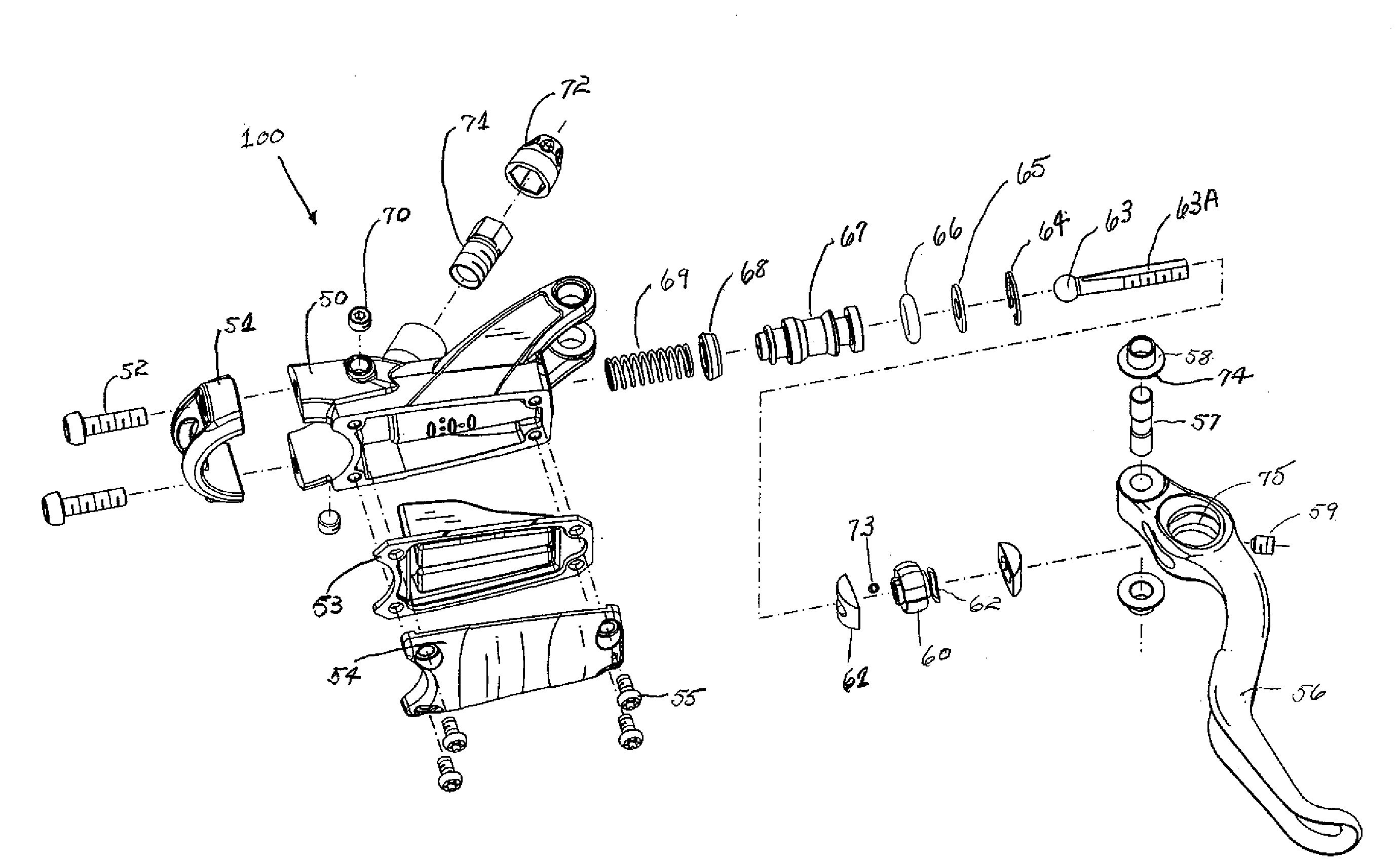
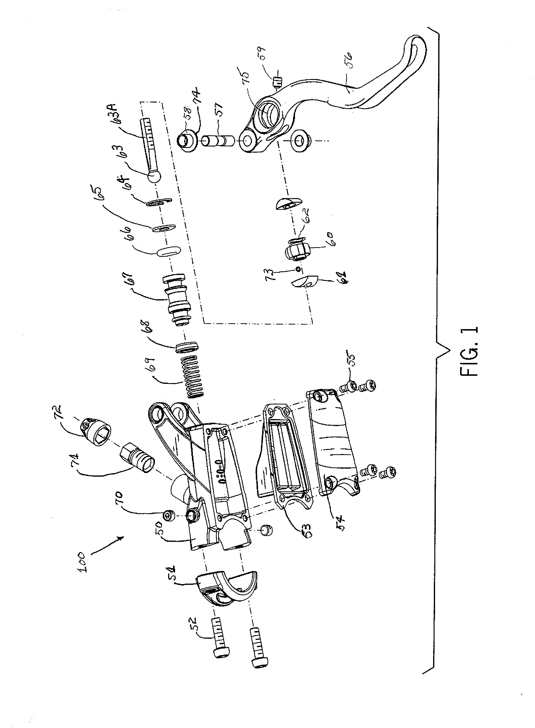
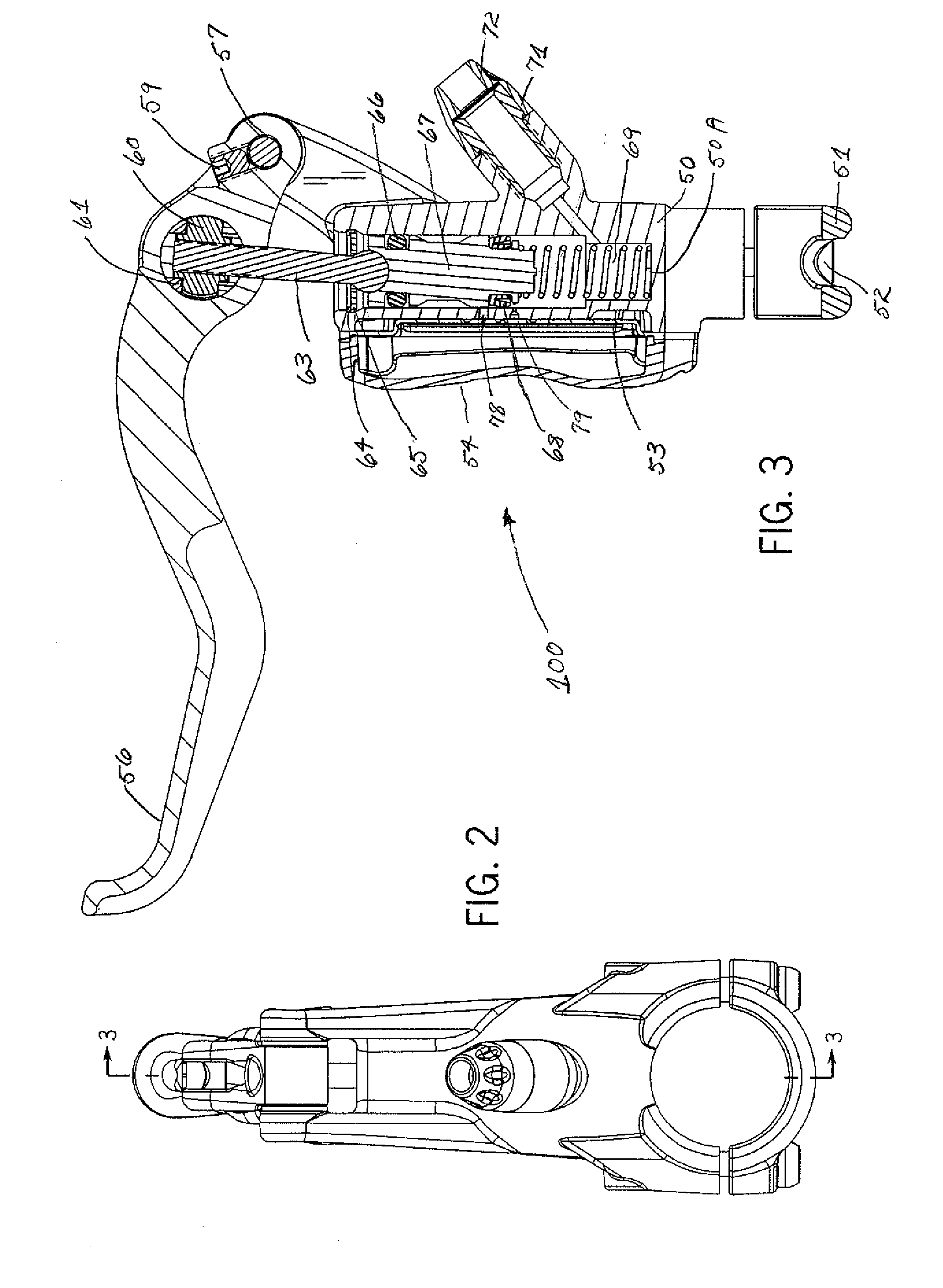
[0051]In FIGS. 1-13, a hydraulic brake master cylinder assembly 100 is shown. A body 50 is attached to a handlebar (not shown) on a bicycle or off-road vehicle by means of a clamp 51 and clamp screws 52. A bladder 53 is fixed to the body 50 by a reservoir cap 54 and reservoir cap screws 55. The space between the bladder 53 and the body 50 defines the reservoir fluid volume, while the space between the bladder 53 and the reservoir cap 54 defines the reservoir expansion volume.

[0052]A lever 56 is pivotally attached to the body 50 by a pivot pin 57 and set screw 59. The pivot pin 57 is necked down towards the center so that it cannot be removed when the set screw 59 is installed. The pivot pin 57 rotates relative to the body 50 on pivot pin bushings 58. The pivot pin bushings 58 each have a flange 74 that keep them retained once the pivot pin 57 is installed and allow the lever 56 to rotate smoothly.

[0053]A pushrod 63 is pivotally attached to the lever 56 by means of an adjuster nut 60...

third embodiment

[0068]A preferred embodiment of the lever 80 is shown in FIGS. 20-21. The end of the lever 80 that accepts a pivot pin 81 and an adjuster bushing 83 is split into two legs 80A. In a third embodiment, as shown in FIGS. 22-24, the end of the lever 80 is pivotally attached to the body 50 by a pivot pin 85 and clip 86. The clip 86 is located between the lever legs 80A. This arrangement allows for a reduced number of parts as well as reduced weight and improved appearance.

fourth embodiment

[0069]FIGS. 25-27 show a fourth embodiment utilizing the split end of lever 80. The body 90 has single flange 90A that supports the pivot pin 91 and lever 80 between the lever legs 80A. The pivot pin 91 is necked down towards the center so that it cannot be removed when the set screw 59 is installed. This arrangement allows for reduced weight, a reduced number of parts, and improved appearance.


PUM


Abstract

A hydraulic brake master cylinder is provided that is compact and light in weight. The master cylinder has a reservoir shape that provides increased reservoir expansion volume. The master cylinder also provides gear shifter operation clearance and a comfortable lever that allows easy adjustment without the use of tools. The lever has defined increments of adjustment which make it easy to use. The invention also includes a method of bleeding air from the system without requiring reorientation of the master cylinder. The retention methods for the various lever embodiments shown allow for easy and inexpensive retention of the lever and also provide for reduced overall weight and cost.

Description

FIELD OF THE INVENTION[0001]In general, the inventive arrangements relate to brakes and braking systems, and more specifically, to hydraulic brake master cylinders for bicycles or off-road vehicles.BACKGROUND OF THE INVENTION[0002]The general operation of hydraulic brake master cylinders for bicycles or off-road vehicles is well known. The brake system includes a reservoir housing hydraulic fluid. The brake system operates by rotation of a lever which applies force to a piston. When force is applied, the piston slides in a longitudinal bore thereby producing an increase in hydraulic pressure in the bore which pressurizes the brake system. One or more fluid paths connect the piston bore to the reservoir. The reservoir contains a bladder that can expand and contract based on the needs of the system.[0003]When the lever is in its free state, also known as the “home” position, its distance from the handlebar is typically adjustable. Current adjusters are difficult to use and levers typi...

Claims


Application Information

Patent Timeline
Patent Type & Authority Applications(United States)
IPC IPC(8): B60T11/26
CPCB60T11/22Y10T74/20612F16C11/02B62L3/023F16C2326/20
Inventor JONES, CHRISTOPHER S.SCHUELKE, JASONTHOMAS, JOHN L.TRAVIS, RICHARD
Owner HAYES BICYCLE GROUP
Why Eureka
Try Eureka