

Force aid system for braking
A technology of brake booster and brake pedal, applied in the direction of brakes, brake transmission devices, vehicle components, etc., can solve the problems of many power booster systems, unstable booster, complex structure, etc., so as to reduce the number of uses and stabilize the booster effect. , the effect of simplifying the system structure
- Summary
- Abstract
- Description
- Claims
- Application Information
AI Technical Summary
Problems solved by technology
Method used
Image

Examples
Embodiment Construction
[0013] The present invention will be further described below in conjunction with the accompanying drawings and specific embodiments.
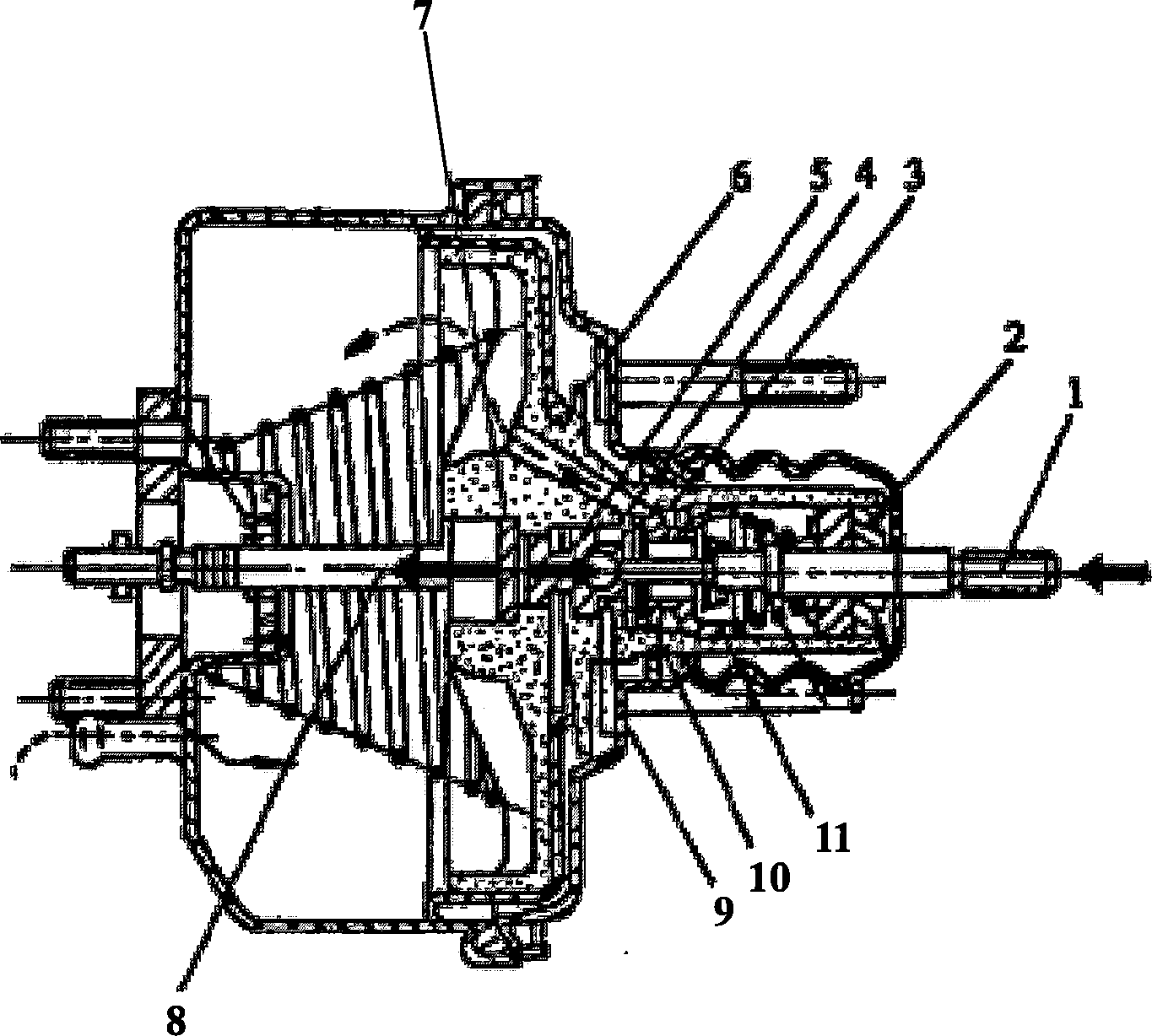
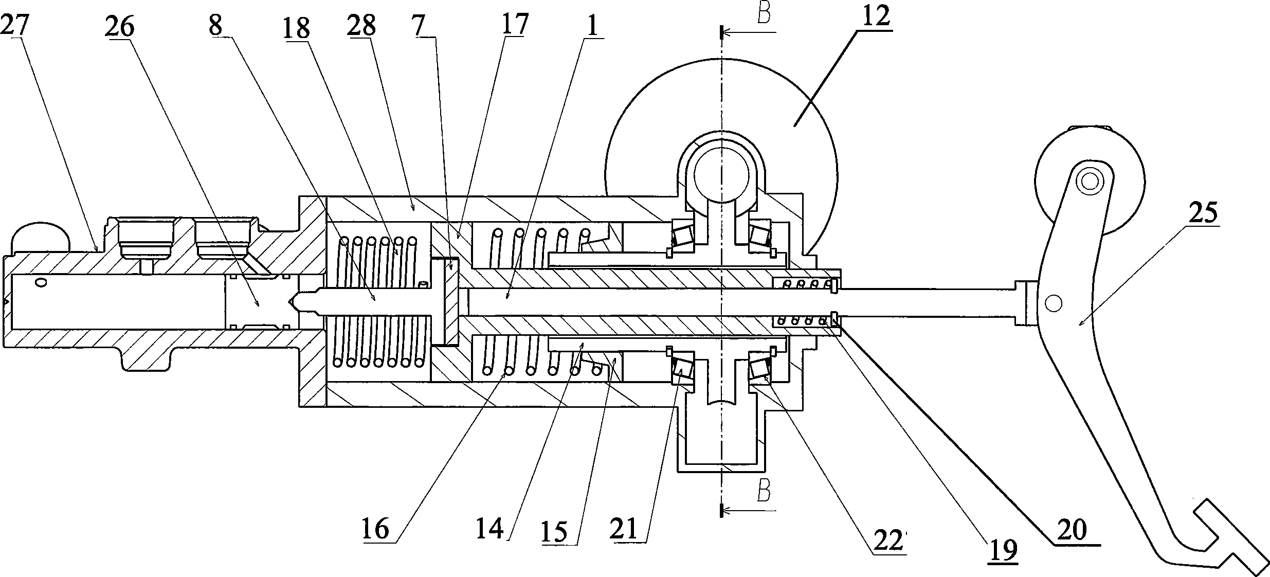
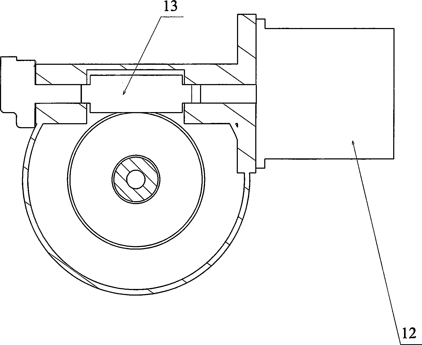
[0014] According to a specific embodiment of the present invention, such as figure 2 and 3 As shown, the brake booster system provided by the present invention includes a pedal push rod 1, a rubber reaction disc 7, a master cylinder push rod 8, a brake pedal 25 and a housing 28, and the brake booster system also includes a motor 12, a worm 13 , Worm wheel 14, nut 15, spring 16, piston 17, return springs 18 and 19, retaining ring 20 and bearings 21 and 22.
[0015] Wherein, the motor 12 is connected with the worm 13 . The worm 13 meshes with a worm wheel 14 . Worm wheel 14 is connected to housing 28 by bearings 21 and 22 and is free to rotate about its axis within the cavity of housing 28 . And the worm wheel 14 is connected with the nut 15 by threads, preferably the thread has a self-locking function, so only when the worm wheel 14 rotates...
PUM
 Abstract
Description
Claims
Application Information