Capacitive touch panel

Inactive Publication Date: 2014-06-05
WINTEK CORP
View PDF3 Cites 25 Cited by
  • Summary
  • Abstract
  • Description
  • Claims
  • Application Information

AI Technical Summary

Benefits of technology

[0007]The invention is directed to a capacitive touch panel capable of providing multi-touch function, filtering off noises and reducing malfunction by ch

Problems solved by technology

Since the capacitance induced by far-field lines of electric force is far less than the capacitance induced by near-field lines of electric force, the capacitance variation of the sensing circuit is little and is ha

Method used


Image

  • Capacitive touch panel
  • Capacitive touch panel
  • Capacitive touch panel

Examples


Example

First Embodiment

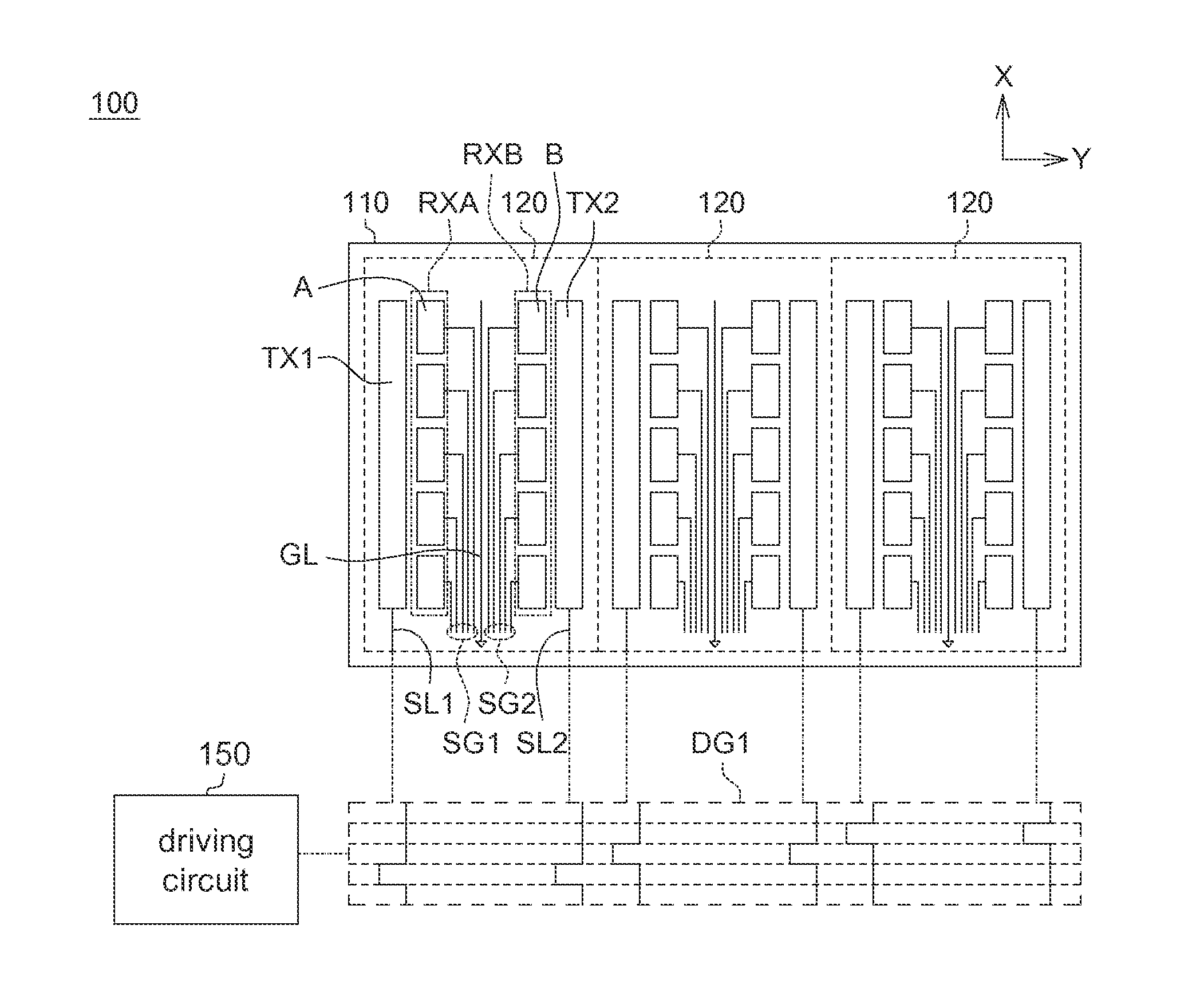
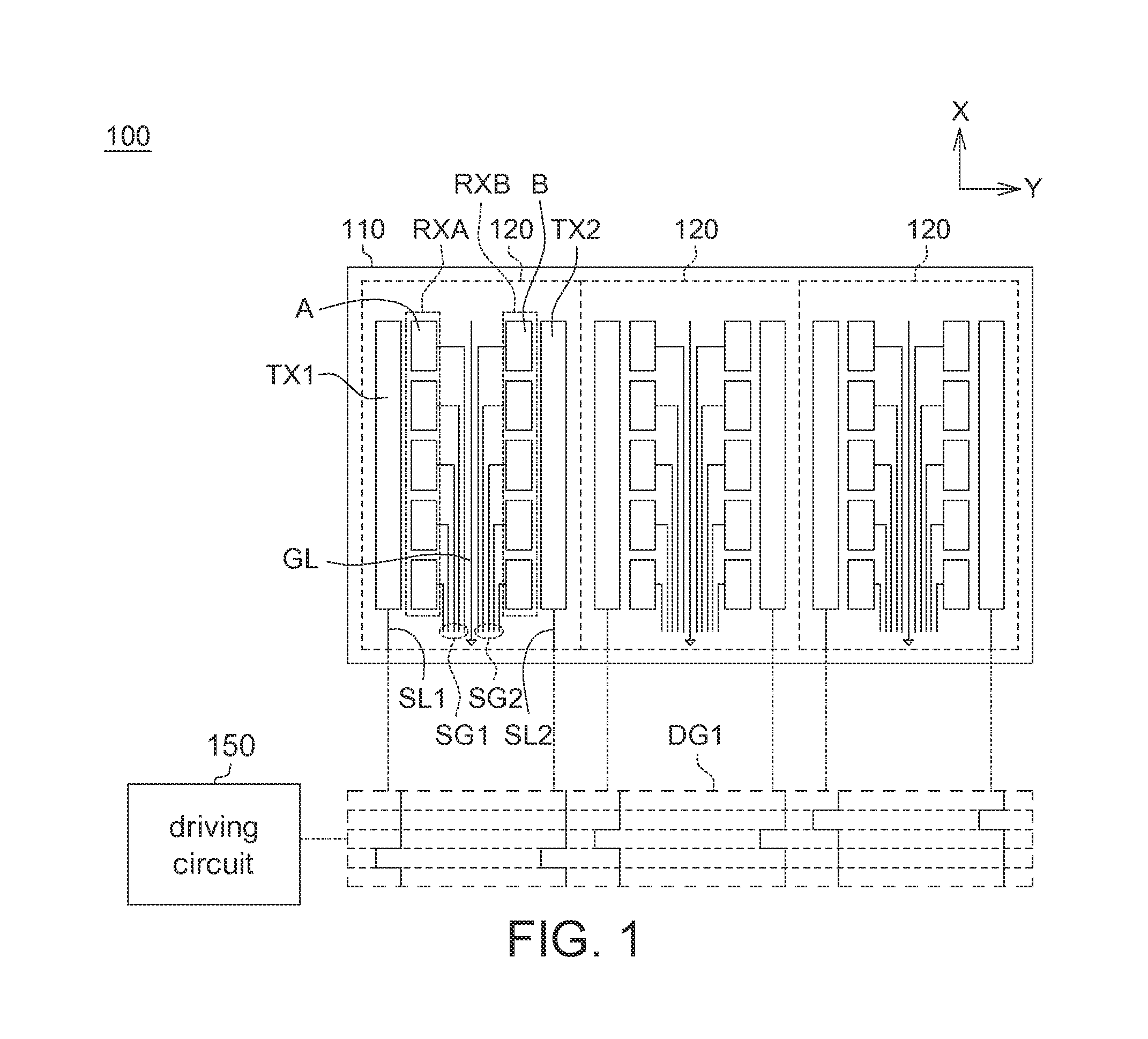
[0018]Referring to FIG. 1, a schematic diagram of a capacitive touch panel 100 according to an embodiment of the invention is shown. Let a single-layer capacitive touch panel be taken for example. The single-layer capacitive touch panel comprises a substrate 110 and a plurality of approach sensing units 120. The substrate 110 can be formed by glass or plastics. The approach sensing units 120 are formed on the substrate 110 and sense the approach of an object (such as a finger) to generate an approach sensing signal. The sensing signal can be capacitance variation, for example. Each approach sensing unit 120 includes a first driving electrode TX1, a second driving electrode TX2, a first sensing electrode unit RXA and a second sensing electrode unit RXB. The first sensing electrode unit RXA and the second sensing electrode unit RXB are adjacent to each other and disposed between the first driving electrode TX1 and the second driving electrode TX2. The first sensing ele...

Example

Second Embodiment

[0031]Referring to FIG. 3, a schematic diagram of a capacitive touch panel 200 according to an embodiment of the invention is shown. The capacitive touch panel 200 comprises a substrate 210 and a plurality of approach sensing units 220. The substrate 210 can be formed by glass or plastics. The approach sensing units 220 are formed on the substrate 210 for sensing the approach of an object (such as a finger) to generate an approach sensing signal. The sensing signal can be capacitance variation. The first driving electrode TX1 and the second driving electrode TX2 are adjacent to each other and disposed between the first sensing electrode unit RXA and the second sensing electrode unit RXB. The first sensing electrode unit RXA further includes a plurality of first sensing electrodes A. The second sensing electrode unit RXB further includes a plurality of second sensing electrodes B. In each approach sensing unit 220, the first sensing electrodes A and the second sensin...


PUM


Abstract

A capacitive touch panel including a substrate and a plurality of approach sensing units disposed on the substrate is provided. Each approach sensing unit comprises a first driving electrode, a second driving electrode, a first sensing electrode unit and a second sensing electrode unit. The first and second driving electrodes are arranged in parallel along an axis. The first and second sensing electrode units are arranged along an axis and sense the approach of an object to generate a first approach sensing signal and a second approach sensing signal, respectively. The first and second sensing electrode units are adjacent to each other and disposed between the first and second driving electrodes or the first and second driving electrodes are adjacent to each other and disposed between the first and second sensing electrode units.

Description

[0001]This application claims the benefit of Taiwan application Serial No. 101145742, filed Dec. 5, 2012, the subject matter of which is incorporated herein by reference.BACKGROUND OF THE INVENTION[0002]1. Field of the Invention[0003]The invention relates in general to a touch panel, and more particularly to a capacitive touch panel.[0004]2. Description of the Related Art[0005]When a single-layer capacitive touch panel is touched by a finger, major far-field lines of electric force will be induced by finger resulting in the variation of the capacitance. Since the capacitance induced by far-field lines of electric force is far less than the capacitance induced by near-field lines of electric force, the capacitance variation of the sensing circuit is little and is hard to detect.[0006]Moreover, most conventional single-layer capacitive touch panels only have single touch function, and may malfunction when the conventional single-layer capacitive touch panels are interfered by noises.S...

Claims


Application Information

Patent Timeline
IPC IPC(8): G06F3/044
CPCG06F3/044G06F3/04166G06F3/0443
Inventor CHANG, TING-YUSU, KUO-CHANGLIAO, SHIAO-HUIHSU, CHING-FUHO, KUN-CHANGWU, FA-CHEN
Owner WINTEK CORP
Why Eureka
Try Eureka