Touch based elevator call panel

a technology of elevator call panel and touch, which is applied in the field of elevator system, can solve the problems of awkward implementation of call panel of desired shape and size, inconvenient cleaning, and inability to meet the needs of elevators, and achieve the effects of preventing or at least reducing malfunctions resulting from vandalism, saving costs, and being easy to clean

Active Publication Date: 2012-12-25
KONE CORP
View PDF24 Cites 15 Cited by
  • Summary
  • Abstract
  • Description
  • Claims
  • Application Information

AI Technical Summary

Benefits of technology

[0019]With the call panel according to the invention numerous advantages are achieved compared to prior-art solutions. The call panel according to the invention is advantageous to manufacture because essentially cheap display elements that are already in mass production can be used to achieve the desired layout, i.e. form. Cost savings can also be achieved because the display elements do not need to comprise pre-integrated touch sensors because in the solution according to the invention only one touch sensor that covers essentially the front surface of the call panel is used, regardless of the amount of display elements. The construction of the call panel is universal, in which case the needs of the installation site can be taken into account better in the different deliveries and at the same time savings can be achieved in the manufacturing costs of the call panel. In the solution according to the invention the whole front surface of the call panel can also be effectively utilized by covering the active areas and the passive areas with the same touch sensor and by specifying touch-sensitive pushbuttons for both areas. By covering the whole front surface of a call panel with a continuous front plate, the components inside the call panel can be protected from detrimental environmental impacts, such as e.g. dust, and at the same time malfunctions resulting from vandalism can be prevented or at least reduced. A continuous front plate is also easy to clean and to keep tidy. By making the front panel semitranslucent, behind which the components and other structures of the call panel can be hidden from view, the construction can be made to be simple and neat. As a result of the invention, the fault tolerance of a call panel can be improved by changing the functions of the call panel in fault situations so that at least the basic functions of the call panel can be used by passengers also in different fault situations. In the solution according to the invention a passive area can be advantageously utilized by disposing fixed embossed pushbuttons in the passive area, in which case the active areas remain for the use of dynamically formable touch-sensitive pushbuttons.

Problems solved by technology

One problem with touch-sensitive displays is, however, that the display elements are manufactured according to certain standard dimensions, in which case implementation of call panels of the desired shape and size is awkward.
A corresponding space problem can arise if it is desired to dispose a call panel on a floor level in the space between adjacent elevator doors.
Since the display elements of touch-sensitive displays that are manufactured as mass products are generally 4:3 or 16:9 in aspect ratio, they are not at all suited as such for use in a call panel of elevators within the scope of the set layout requirements.
The solution, however, easily becomes complex and expensive, because each display element comprises, in addition to the display element itself, also a touch sensor connected to the display element and the control electronics required by it.
Furthermore, conventional touch-sensitive displays cannot be protected from environmental impacts nor from vandalism, which easily results in different malfunctions in elevator operation.
Since the touch-sensitive surface in conventional touch-sensitive displays covers only the area covered by the display element, the area outside the display elements remains unutilized from the call panel.
All in all, conventional touch-sensitive displays set considerable limitations, in relation to layout as well as in relation to appearance, for the design of call panels applicable to elevator use.

Method used


Image

  • Touch based elevator call panel
  • Touch based elevator call panel
  • Touch based elevator call panel

Examples


Embodiment Construction

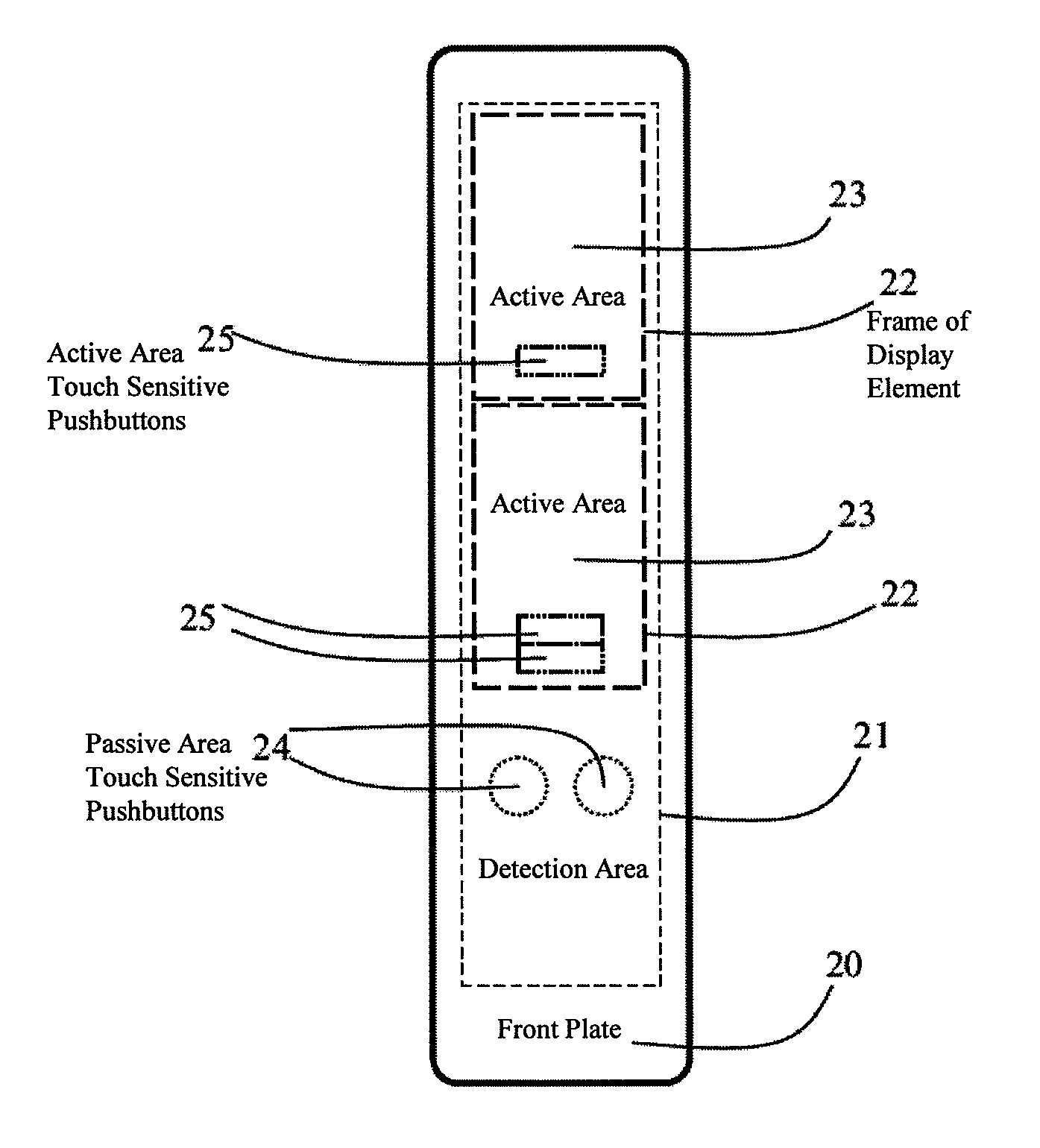
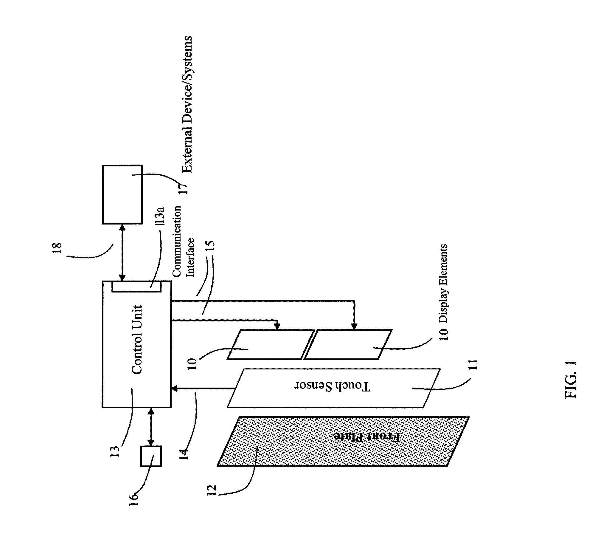
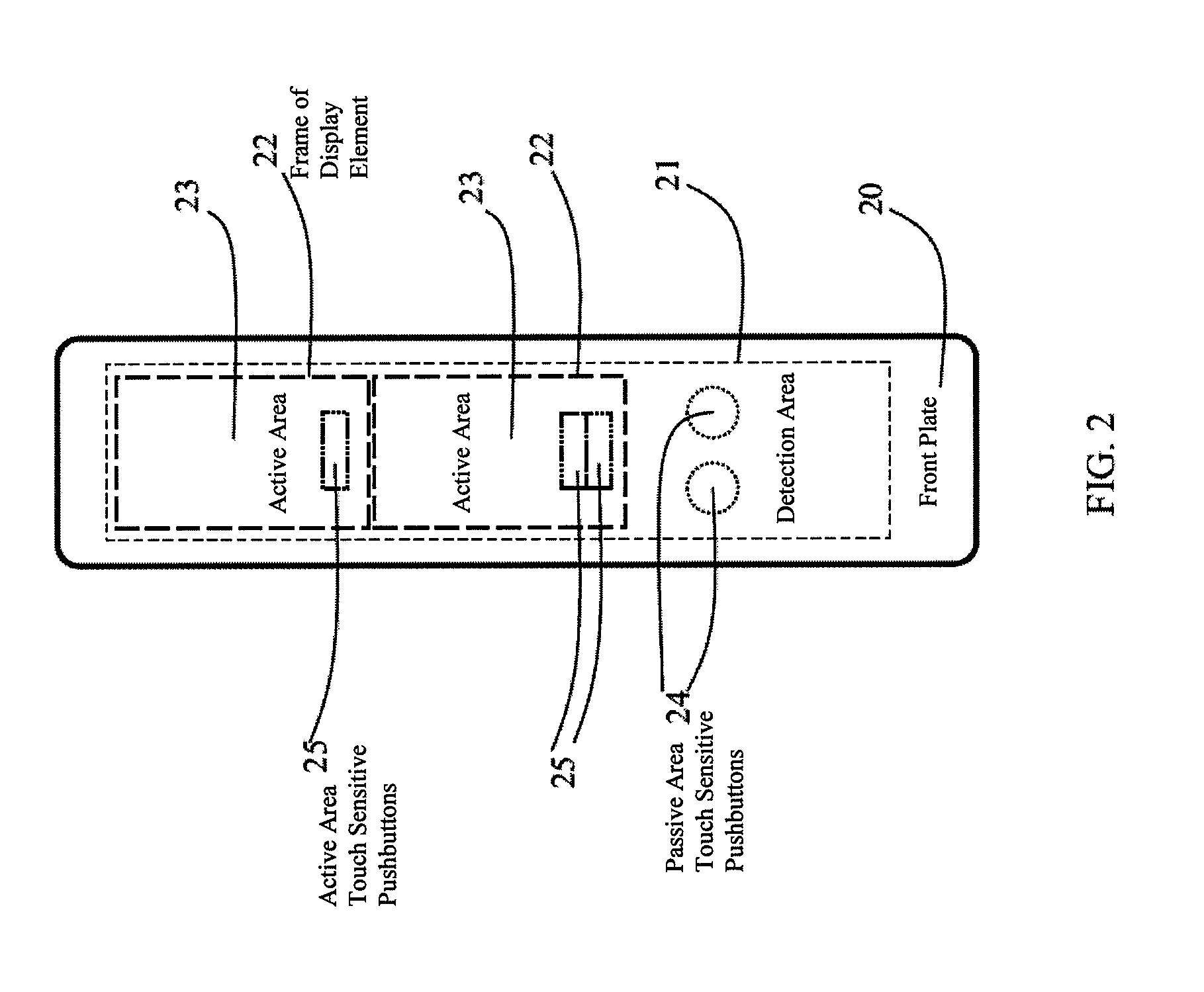
[0026]FIG. 1 presents the basic components of a call panel according to the invention, which are: display elements 10, a touch sensor 11, a front plate 12, and also a control unit 13. FIG. 1 contains two display elements 10, but the number of them can also be different, depending on the installation site. The display elements are installed in a vertical attitude such that their shorter sides are horizontal, in which case the aspect ratio will be e.g. 3:4 or 9:16. The display elements are installed with their shorter sides facing each other to achieve an elongated lay-out. The display elements are e.g. flat TFT displays (TFT-LCD). The front surface of the front plate 12 forms the front surface of the call panel, in connection with which front surface a touch sensor 11 is integrated so that the detection area covers essentially the whole front surface of the front plate. The front panel is partly translucent so that the graphic information produced with the display elements is visible...


PUM


Abstract

The present invention presents a call panel of an elevator or of an elevator system including one or more display elements, a front plate covering the call panel, in connection with which front plate a touch sensor is fitted, and also a control unit to which the display elements and also the touch sensor are connected. The detection area of the touch sensor covers both an active area, and a passive area, where the active area additionally utilizes display elements, while the passive area lacks display capability and remains outside at least some of the aforementioned active area, in which one or more touch-sensitive pushbuttons are disposed in the passive area. The control unit is arranged to react to a touch of the touch-sensitive pushbuttons specified for the aforementioned detection area.

Description

CROSS-REFERENCE TO RELATED APPLICATIONS[0001]This application is a Bypass Continuation of PCT International Application No. PCT / FI2010 / 000012 filed on Feb. 16, 2010, which claims priority under 35 U.S.C. 119 (a) to Patent application No. 20090054 filed in Finland, on Feb. 16, 2009. The entire contents of all of the above applications is hereby incorporated by reference.FIELD OF THE INVENTION[0002]The invention relates to elevator systems. More particularly the invention relates to elevator system call panels that are implemented with touch-sensitive pushbuttons.BACKGROUND OF THE INVENTION[0003]Elevator systems normally comprise call-giving appliances both on the floor levels and in the elevator cars, with which appliances calls are given for receiving an elevator car at the call floor and for sending the elevator car to the desired destination floor. So-called destination call systems are also known in the art, in which systems the passenger expresses his / her destination floor alrea...

Claims


Application Information

Patent Timeline
Patent Type & Authority Patents(United States)
IPC IPC(8): B66B1/34
CPCB66B1/463B66B1/461
Inventor POUTIAINEN, VESARUSANEN, NIKO
Owner KONE CORP
Why Eureka
Try Eureka