Device and methods for testing quality of welding joints

a technology for welding joints and devices, applied in non-electric welding apparatuses, materials strength using single impulsive force, instruments, etc., can solve the problems of time-consuming and therefore high cost of conventional iterative processes, and achieve the effect of convenient and economical us

Active Publication Date: 2014-06-12
EMBRAER SA
View PDF2 Cites 5 Cited by
  • Summary
  • Abstract
  • Description
  • Claims
  • Application Information

AI Technical Summary

Benefits of technology

[0006]It would therefore be desirable if devices and methods were provided locally at a friction stir or other welding machine which could more easily and economically enable a manufacturer to verify and test the quality of welding joint strengths on coupons. It is towards providing such devices and methods that the embodiments disclosed herein are directed.

Problems solved by technology

As can be appreciated, this conventional iterative process is quite time consuming and is therefore quite expensive.

Method used


Image

  • Device and methods for testing quality of welding joints
  • Device and methods for testing quality of welding joints
  • Device and methods for testing quality of welding joints

Examples


Embodiment Construction

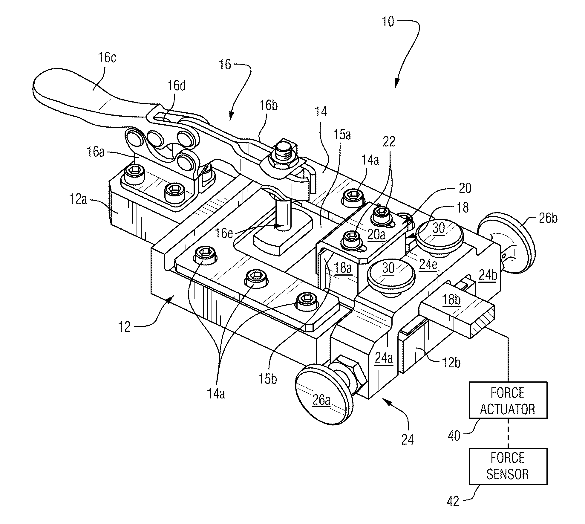
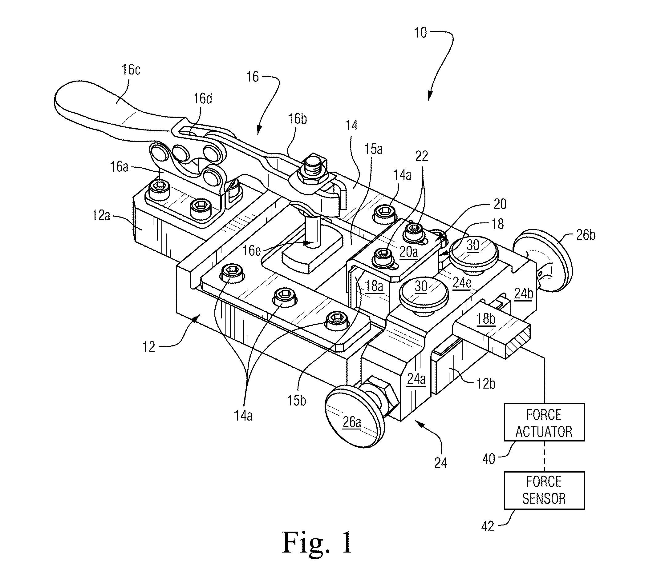
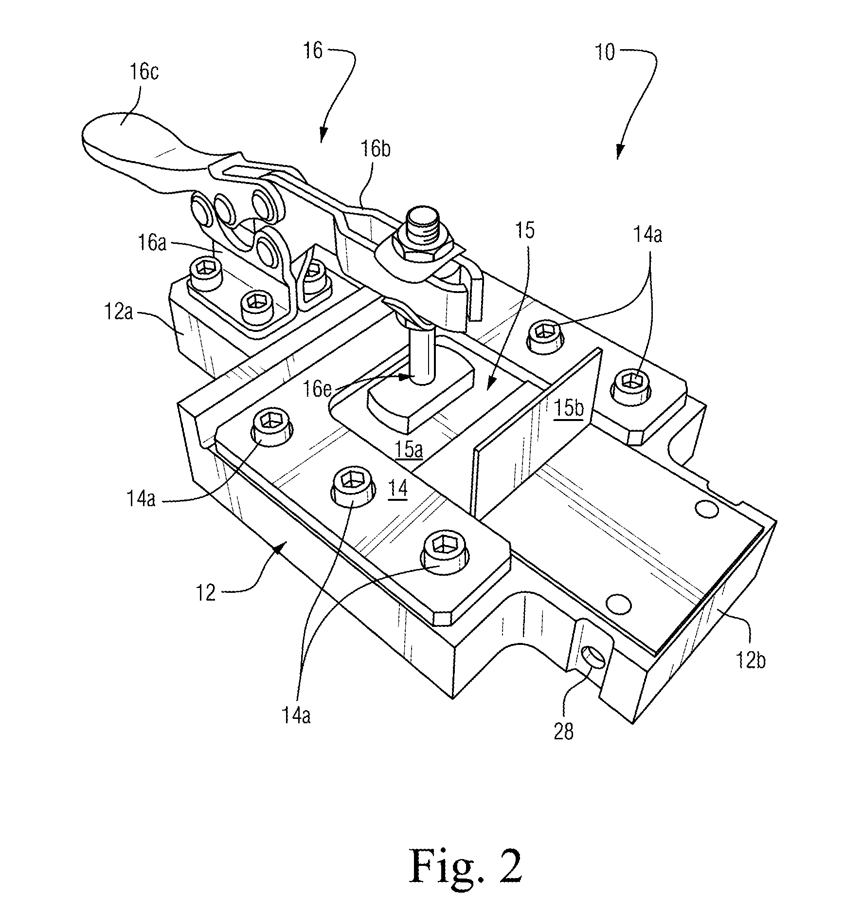
[0019]Accompanying FIG. 1 shows an assembly view of a testing device 10 in accordance with an embodiment of the present invention for testing the quality of bond strengths of friction stir welded coupons. Specifically, the device 10 includes a base 12 having a generally U-shaped coupon receiver 14 fixed to an upper face thereof (e.g., by means of bolts 14a). The coupon receiver 14 is thereby adapted to receive the lower part 15a of a test specimen (coupon) 15. As shown, the lower part 15a is in a planar surface having an upper L-shaped part 15b bonded thereto by FSW so that an upright portion of the L-shaped part 15b is essentially at a right angle to the lower planar part 15a (see FIG. 2). Alternatively, the lower part 15a may have a non-planar surface geometry, e.g., in the form of a curved surface. In such a case, a corresponding region of the upper face of the base 12 would then likewise be curved so as to conformably match the curved surface of the lower part 15a.

[0020]The bas...


PUM

PropertyMeasurementUnit
weld strengthaaaaaaaaaa
reciprocal axial movementsaaaaaaaaaa
axial movementsaaaaaaaaaa

Abstract

Devices and methods are provided for testing weld strengths of a test coupon joint. A test coupon is positionally fixed to a base of the testing device. A punch assembly having a head portion is provided so as to exert an axial force against an upright part of the test coupon to thereby determine weld strength between the planar and upright parts of the test coupon (e.g., a maximum force at which weld failure occurs).

Description

CROSS-REFENCE TO RELATED APPLICATION[0001]The present application is based on and claims domestic priority benefits under 35 USC §119(e) from U.S. Provisional Patent Application Ser. No. 61 / 679,362 filed on Aug. 3, 2012, the entire content of which is expressly incorporated hereinto by reference.FIELD[0002]The embodiments disclosed herein relate generally to devices and methods for testing the quality of weld strengths, especially the strength of welding joints formed by friction stir welding (FSW) techniques.BACKGROUND AND SUMMARY[0003]Friction stir welding (FSW) is commonly used to weld two or more work pieces formed of various metals, such as aluminum, magnesium, copper, titanium, steel and the like, one to another. FSW techniques may be employed satisfactorily to form welded lap joint, L-joint and / or T-joint.[0004]During conventional FSW processes (including continuous and segmented friction stir welding), a FSW tool having a specific geometry is forced into, and traversed throu...

Claims


Application Information

Patent Timeline
Patent Type & Authority Applications(United States)
IPC IPC(8): B23K31/12G01N3/30
CPCB23K20/122B23K31/125G01N3/00G01N2203/0296
Inventor MIYAZAKI, MARCOS HIDEKIGONCALVES, MARCOS ANTONIO BATISTAVILIOTTI, ANDREZA SOMMERAUER FRANCHIMFERNANDEZ, FERNANDO FERREIRA
Owner EMBRAER SA
Why Eureka
Try Eureka