Medium separating and supplying mechanism

Inactive Publication Date: 2014-06-12
OKI ELECTRIC IND CO LTD
View PDF1 Cites 0 Cited by
  • Summary
  • Abstract
  • Description
  • Claims
  • Application Information

AI Technical Summary

Benefits of technology

[0048]According to the above-described aspect of the present invention, there may be provided a medium separating and supplying mechanism which, because it may increase the size of the limit angle, may suppress a situation where a medium is held by a supply feed roller and a supply roller, there

Problems solved by technology

Further, there are also cases where the mediums P end up becoming skewed while being sup

Method used


Image

  • Medium separating and supplying mechanism
  • Medium separating and supplying mechanism
  • Medium separating and supplying mechanism

Examples


first exemplary embodiment

1. First Exemplary Embodiment

[1-1. Configuration of Medium Separating and Supplying Mechanism]

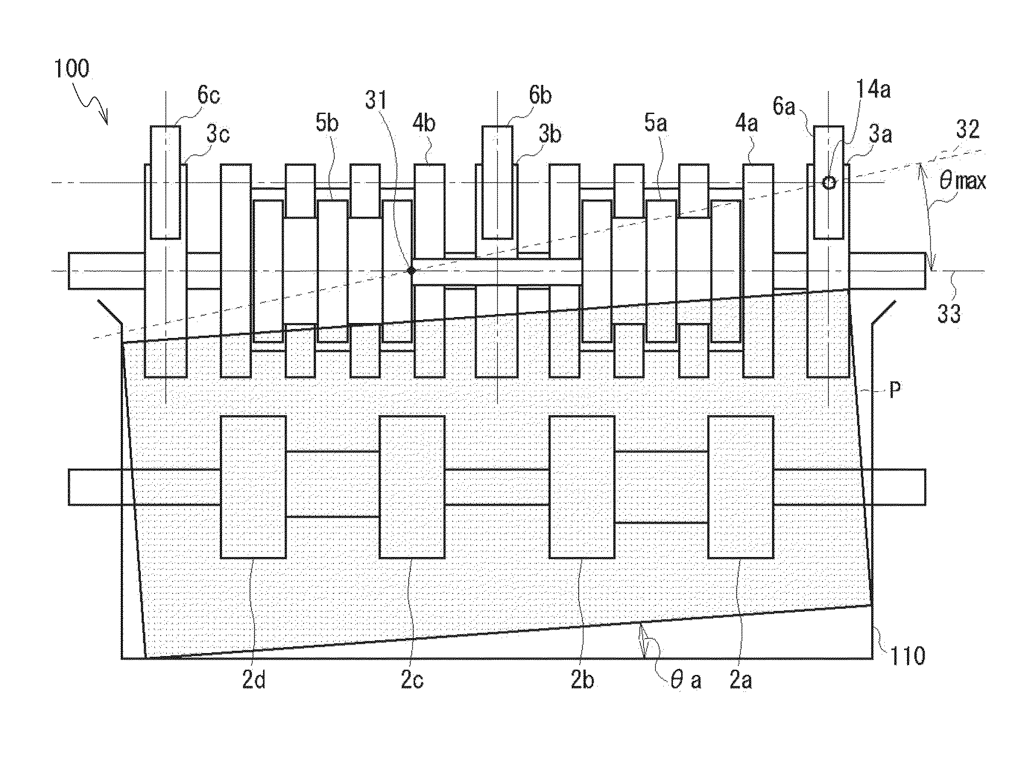
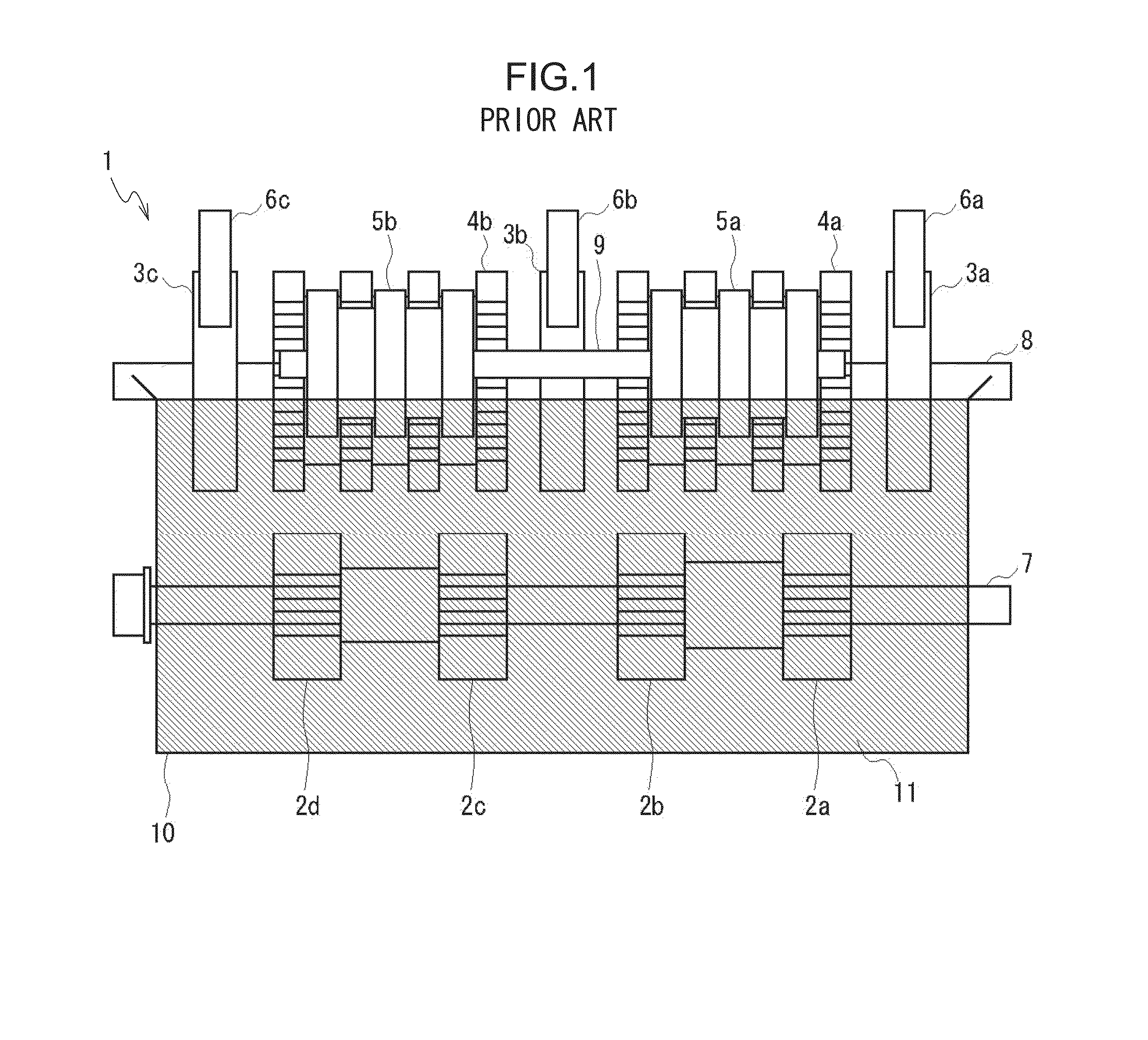
[0087]First, a first exemplary embodiment will be described. FIG. 19A shows the conventional medium separating and supplying mechanism 1, and FIG. 19B shows a medium separating and supplying mechanism 100 in the first exemplary embodiment. The medium separating and supplying mechanism 100 has the same configuration as that of the conventional medium separating and supplying mechanism 10 except that the side surface guide 10 is replaced with a side surface guide 110.

[0088]The side surface guide 110 has a supply direction length L11 and a width direction length W11 that are shorter than a supply direction length L1 and a width direction length W1 of the side surface guide 10.

[0089]Specifically, the supply direction length L11 and the width direction length W11 of the side surface guide 110 are determined in the following way.

[0090]As shown in FIG. 20, PW, PH, and PD denote a supply direction ...

second exemplary embodiment

2. Second Exemplary Embodiment

[2-1. Configuration of Medium Separating and Supplying Mechanism]

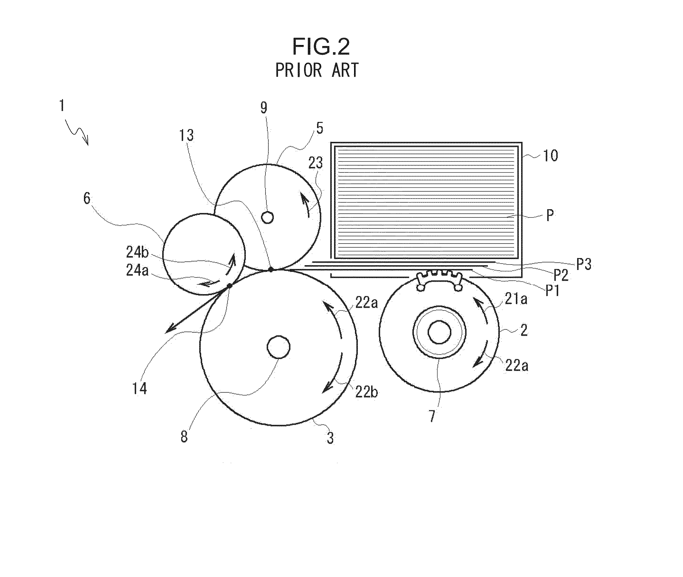
[0126]Next, a second exemplary embodiment will be described. (1) of FIG. 29 shows the conventional medium separating and supplying mechanism 1, and (2) of FIG. 29 shows a medium separating and supplying mechanism 200 in a second exemplary embodiment. In FIGS. 1) of 29 and (2) of 29, the side surface guide 10 is omitted for convenience of description. Further, in the medium separating and supplying mechanism 200 of the second exemplary embodiment, the side surface guide 110 of the first exemplary embodiment may also be used instead of the side surface guide 10.

[0127]The medium separating and supplying mechanism 200 has a configuration where, compared to the conventional medium separating and supplying mechanism 1, a supply feed roller 203a and supply roller 206a and a supply feed roller 203c and supply roller 206c are each nearer to the center by a distance D1. Other configurations are the ...

third exemplary embodiment

3. Third Exemplary Embodiment

[3-1. Configuration of Medium Separating and Supplying Mechanism]

[0138]Next, a third exemplary embodiment will be described. As shown in FIG. 31 and FIG. 32, a medium separating and supplying mechanism 300 in the third exemplary embodiment is given a configuration including pickup rollers 302, supply feed rollers 303, separation feed rollers 304, separation gate rollers 305, supply rollers 306, shafts 307, 308, and 309, and the side surface guide 10.

[0139]In FIG. 32, the side surface guide 10 is omitted for convenience of description. Further, in the medium separating and supplying mechanism 300 of the third exemplary embodiment, the side surface guide 110 in the first exemplary embodiment may also be used instead of the side surface guide 10.

[0140]The pickup rollers 302 are arranged on and fixed to the shaft 307 in a line in the width direction below the stacking area 11 of the side surface guide 10. The shaft 307 is rotatably supported by bearings and ...


PUM


Abstract

The present invention provides a medium separating and supplying mechanism that may reduce the causes of jams and errors on a conveyance path and so forth from supply onward. Namely, by making the skew angle of a medium less than a limit angle θmax, at which skewing is regard to increase, when the medium reaches a gate portion, the present invention may prevent the medium from rotating at an overlap point in a direction in which the skew angle is increased, which occurs as a result of the medium reaching the overlap point.

Description

TECHNICAL FIELD [0001]The present invention relates to a medium separating and supplying mechanism that uses rollers to separate and supply, one item at a time, paper sheet mediums such as banknotes, for example.BACKGROUND ART [0002]Conventionally, medium separating and supplying mechanisms configured to separate and supply, one item at a time, mediums (banknotes) stacked in an ATM or the like, for example, have been proposed (e.g., see Japanese Patent Application Laid-Open (JP-A) No. 2008-273669).[0003]Specifically, as shown in FIG. 1 to FIG. 3, a medium separating and supplying mechanism 1 is given a configuration including pickup rollers 2 (2a to 2d), supply feed rollers 3 (3a to 3c), separation feed rollers 4 (4a and 4b), separation gate rollers 5 (5a and 5b), supply rollers 6 (6a to 6c), shafts 7, 8, and 9, and a side surface guide 10.[0004]The pickup rollers 2 are arranged in a line in a direction (hereinafter this will also be called a width direction) orthogonal to a directi...

Claims


Application Information

Patent Timeline
IPC IPC(8): B65H3/06B65H9/00
CPCB65H9/002B65H3/06B65H3/063B65H3/5284B65H2404/1316B65H2404/623B65H2701/1912
Inventor OKAMOTO, MASAAKIYOKOKAWA, HIROSHI
Owner OKI ELECTRIC IND CO LTD
Why Eureka
Try Eureka