Line & pipe flexible temperature sensor assembly

a flexible temperature sensor and pipe technology, applied in the field of temperature sensors, can solve the problems of difficult sealing of such a fluid line, difficult direct reading of fluid within a fluid line, and high cost, and achieve the effect of inexpensively reading the surface temperature, quick and easy reading of the surface temperature, and quick and easy opening of the fluid line to insert the sensor

Inactive Publication Date: 2014-06-12
PROCTOR ENG GRP
View PDF5 Cites 45 Cited by
  • Summary
  • Abstract
  • Description
  • Claims
  • Application Information

AI Technical Summary

Benefits of technology

[0023]When the Assembly of the present invention is in operation, the Contact Temperature Sensor resides within a housing which partially surrounds the Contact Temperature Sensor (the “Housing”). More specifically, the Housing is designed to enclose the Contact Temperature Sensor when placed on a Fluid Line, thereby preventing the flow of air (or other fluids) over the Contact Temperature Sensor as it reads a Fluid Line temperature. Accordingly, the Housing is formed to surround the Contact Temperature Sensor on its sides, and cover over the Contact Temperature Sensor on its top. The Housing remains open at its bottom, so that the Contact Temperature Sensor residing within the Housing may rest on the Fluid Line to be measured. The Contact Temperature Sensor Lead, by which the electrical signal generated by the Contact Temperature Sensor may be transmitted to a meter, extends though a channel in the body of the Housing, at a point which is convenient, generally through the top of the Housing. The Housing channel is either preformed or, preferably, created as the material of the Assembly is heated and molded into shape. The Lead may also extend through the body of the Housing at its side if space constraints within a System, particularly surrounding a Fluid Line, make a “low profile” Assembly desirable. In any case, the material of the Housing is formed to close tightly around the Lead, to prevent transmission of air or other fluid between the Lead and the Housing, and from the interior of the Housing to its exterior, or from the exterior of the Housing to its interior.
[0048]A further principal object of the present invention is to provide an operator with a tool for inexpensively reading the surface temperatures of a number of Fluid Lines of a heating or cooling system during installation or maintenance, because the tool may be used to read temperatures in multiple units, for simultaneous reading of multiple Fluid Lines in such Systems.

Problems solved by technology

However, direct reading of the fluid within a Fluid Line is generally not practical, because the fluid within a Fluid Line is generally installed under pressure.
Opening a Fluid Line to insert a Sensor is therefore considered undesirable, as sealing such a Fluid Line is difficult and expensive, and may ultimately not be successful.
The competing factors in determining the size of the Housing include: (i) increased accuracy as a Sensor covers more of the Fluid Line, (ii) decreased effectiveness in keeping the Contact Temperature Sensor insulated from environmental factors as a Sensor increases in size, and (iii) increased cost as a Sensor increases in size.

Method used


Image

  • Line & pipe flexible temperature sensor assembly
  • Line & pipe flexible temperature sensor assembly
  • Line & pipe flexible temperature sensor assembly

Examples


first embodiment

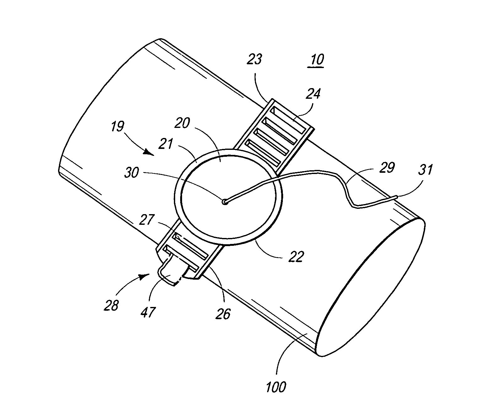
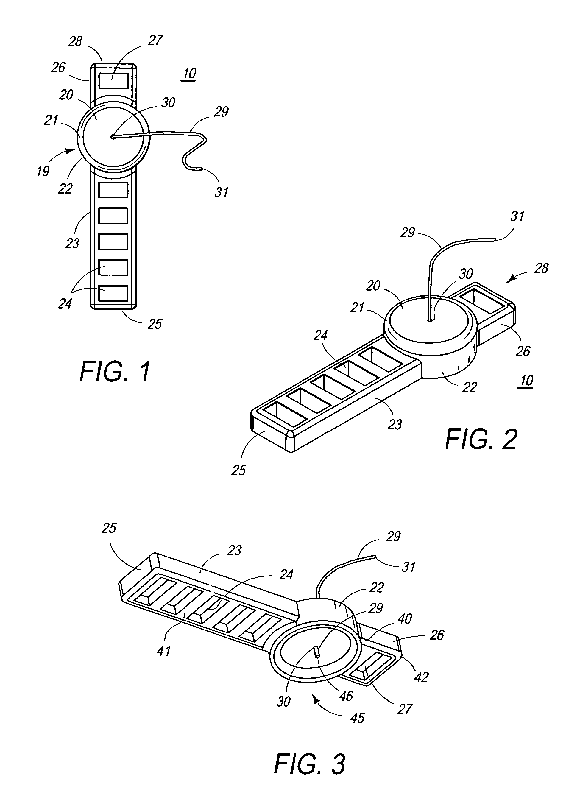
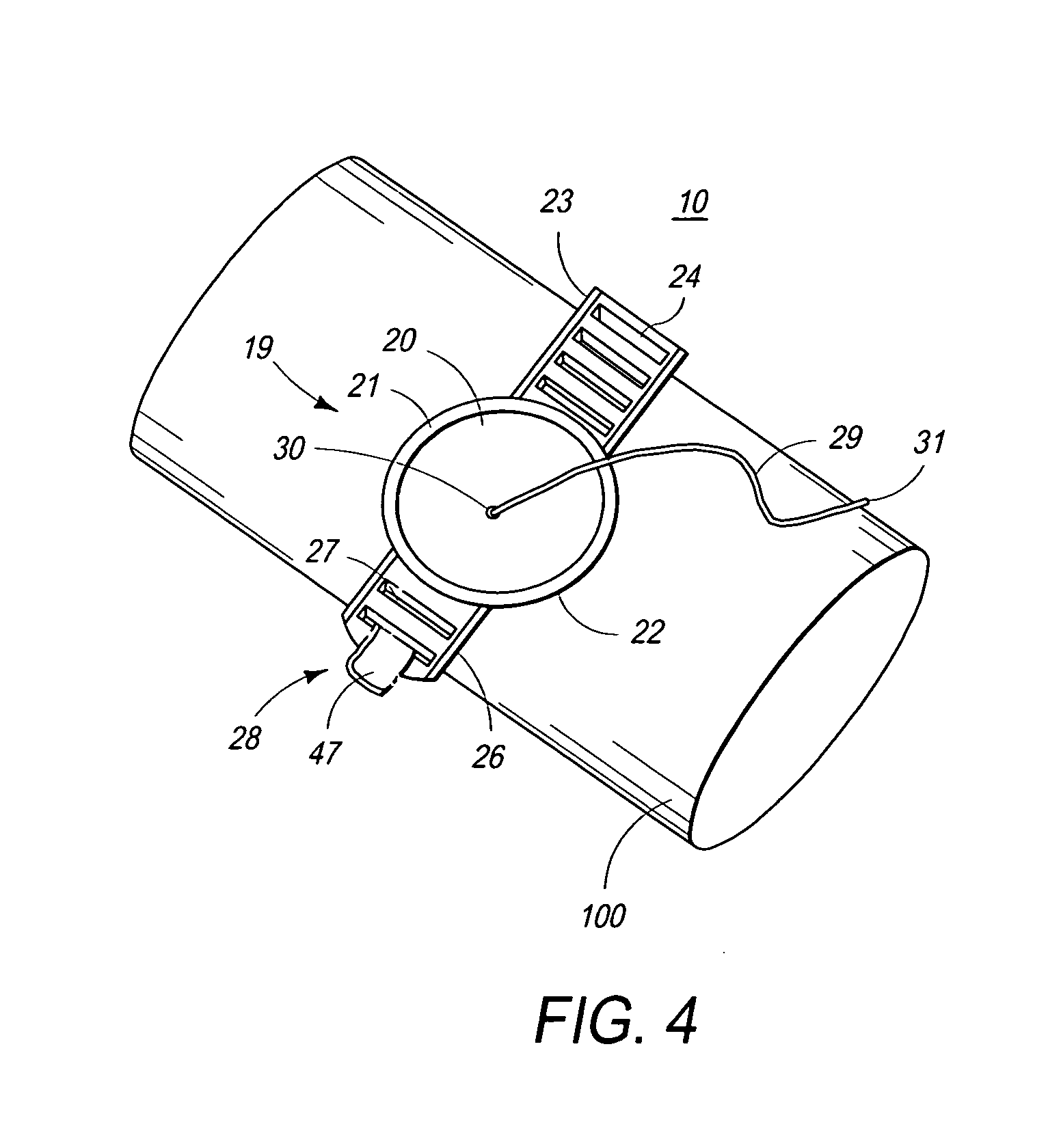
[0055]Referring initially to FIG. 1, the Assembly of the present invention 10 is shown in top down view, i.e. viewed from above the Assembly. In FIG. 1, Housing 19 may be seen, having generally circular form, with shoulders 21 extending to Housing sidewall 22, and Housing top 20. Strap first part 23, with slits 24 formed therein, and strap first part end 25, may also be seen extending from Housing sidewall 22 on one side of Housing 19. Strap second part 26, with at least one slit 27 formed therein, and strap second part end 28, may also be seen extending from Housing sidewall 22 on the opposite side of Housing 19 from strap first part 23. The at least one slit 27 may be fitted with a hook (not shown) or adjustment prong (not shown), or such hook or adjustment prong (not shown) may be formed integrally with strap second part 26, typically at or near its strap second part end 28. Contact Temperature Sensor Lead 29 may be seen emanating from a channel 30 at the center of the top of Hou...

second embodiment

[0061]Turning now to FIG. 5, the Assembly 60 of the present invention is shown in partially disassembled perspective view. In FIG. 5, Housing 69 may he seen, having generally circular form, with shoulders 71 extending to Housing sidewall 72, and Housing top 70. Strap first part 73, with slits 74 formed therein, and strap first part end 75, may also be seen extending from Housing sidewall 72 on one side of Housing 69. Strap second part 76, with at least one slit 77 formed therein, and strap second part end 78, may also be seen extending from Housing sidewall 72 on the opposite side of Housing 69 from strap first part 73. The at least one slit 77 has been fitted with hook 101 near strap second part end 78, and hook end 102 may be seen extending for engagement with one of slits 74, while hook base 103 may be seen anchoring hook 101 through slit 77. Contact Temperature Sensor Lead 79 may be seen emanating from channel 80 at the center of Housing 69 top 70. Lead 79 is electrically connec...


PUM

PropertyMeasurementUnit
flexibleaaaaaaaaaa
resilientaaaaaaaaaa
temperatureaaaaaaaaaa

Abstract

A temperature sensor assembly is disclosed, formed of flexible, resilient, and insulative material, so that a contact temperature sensor, situated in a housing and connected to an electrical meter, may be affixed temporarily or permanently to a (generally) cylindrical tube, pipe, or other “line,” the distal ends of the housing straps stretched and tensioned to press the housing and contact temperature sensor on to the exterior of such fluid line to keep the housing in the correct position on the fluid line, and the distal ends of the straps joined to secure the assembly to the fluid line, so that the temperature on the exterior of the fluid line, and the temperature of the fluid therewithin, may thereby be measured.

Description

TECHNICAL FIELD OF THE INVENTION[0001]The present invention relates to temperature sensors, by which the temperature of an object may be measured. More specifically, the present invention consists primarily of a new design for a temperature sensor assembly (the “Assembly”) which is employed to measure the temperature of a (generally) cylindrical tube, pipe, or other “line,” within which a heating or cooling fluid flows. We refer to such tubes, pipes, or other lines individually in this application as a “Fluid Line,” and collectively as “Fluid Lines,” and temperature sensors used for measuring a Fluid Line individually as a “Sensor,” and collectively as Sensors.[0002]Sensors are used in a variety of industrial and scientific processes and applications, but are particularly necessary to the installation and maintenance of heating, cooling, and refrigeration systems, such as environmental cooling systems (e.g., “air conditioning”). The primary purpose of such a Sensor is to read the te...

Claims


Application Information

Patent Timeline
Patent Type & Authority Applications(United States)
IPC IPC(8): G01K13/02
CPCG01K13/02G01K1/143
Inventor PROCTOR, JOHNHAIRRELL, ADRIANCONANT, ABRAM
Owner PROCTOR ENG GRP
Why Eureka
Try Eureka