

Toilet area for an aircraft cabin, in particular for a flying wing aircraft
a technology for aircraft cabins and toilets, which is applied in the direction of water installation, aircraft ejection means, construction, etc., can solve the problems of high installation costs, in particular in the number of passenger seats, and in the space of the cabin, and achieve the effect of facilitating access to the evacuation exi
- Summary
- Abstract
- Description
- Claims
- Application Information
AI Technical Summary
Benefits of technology
Problems solved by technology
Method used
Image

Examples
first embodiment
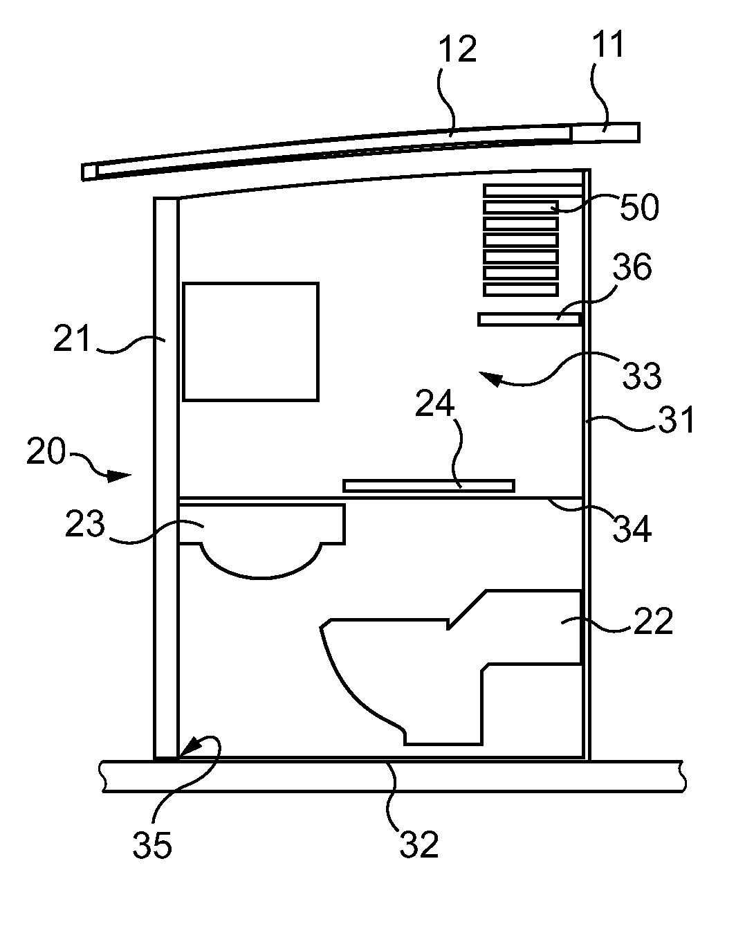
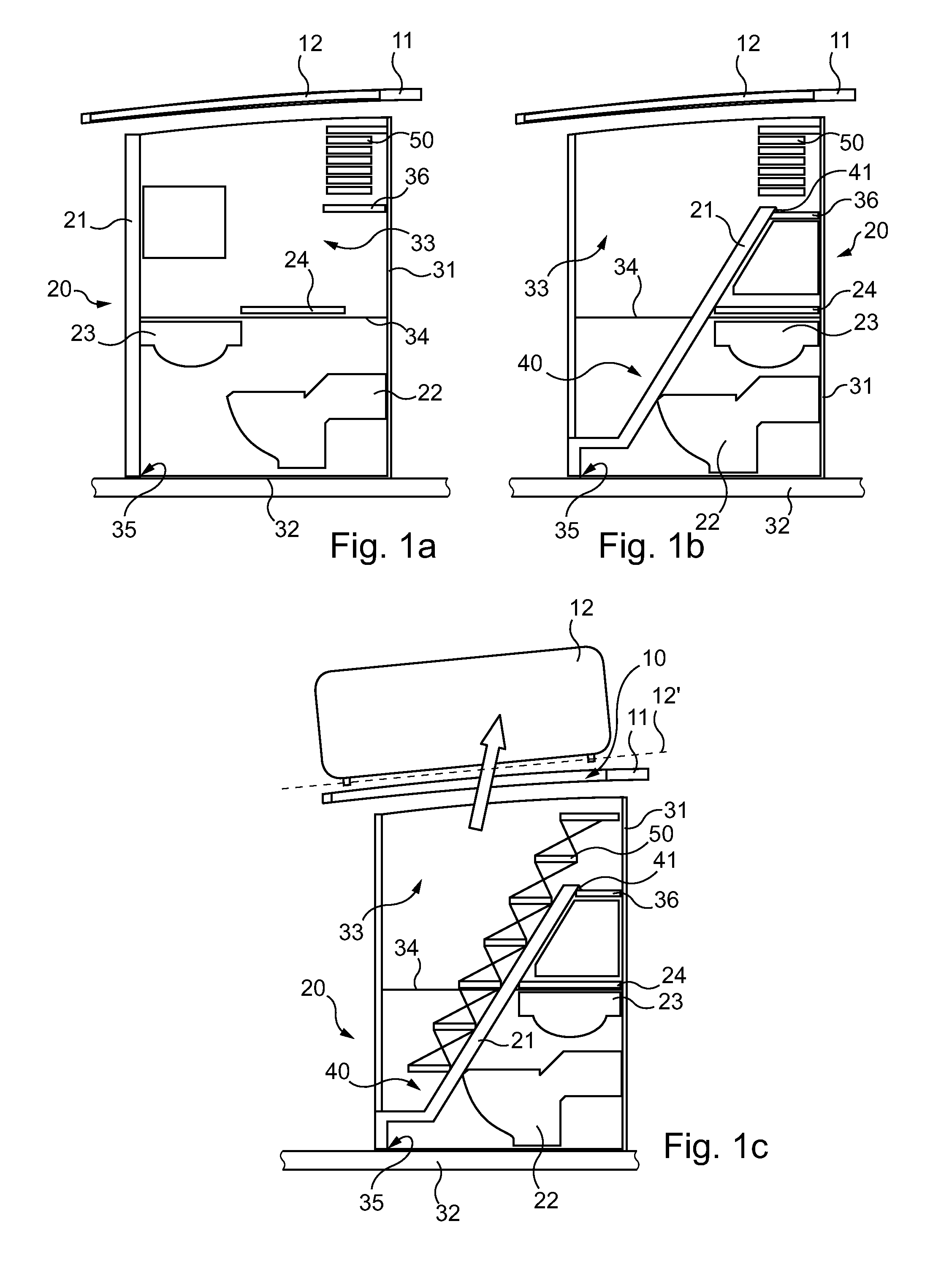
[0061]A description will be given of a toilet area for an aircraft cabin with reference to FIGS. 1a, 1b and 1c.
[0062]In this non-limitative embodiment, the aircraft is a flying wing aircraft.
[0063]A flying wing aircraft is distinguished from a conventional aircraft with a cylindrical fuselage in that the cabin is wide and relatively short in the longitudinal direction of the aircraft, corresponding to its direction of travel.
[0064]In a flying wing aircraft, it is impossible to provide evacuation exits in side walls of the cabin, as the side walls do not open directly to the outside of the aircraft.
[0065]In fact, the side walls of the cabin open at best onto the thick wing of the flying wing aircraft in which the cabin is contained.
[0066]In this type of aircraft, one or more evacuation exits can then be provided in the roof of the cabin, which is substantially horizontal or has a slight slope.
[0067]Thus, as shown in FIG. 1c, an evacuation exit 10 is provided in the roof 11 of the fl...
second embodiment
[0165]A description will now be given with reference to FIGS. 4a and 4b of a toilet area 120.
[0166]In this non-limitative example of implementation, the aircraft is a flying wing aircraft.
[0167]An evacuation exit 110 is provided in the roof 111 and may present a configuration identical to that described above with reference to FIGS. 1a-1c.
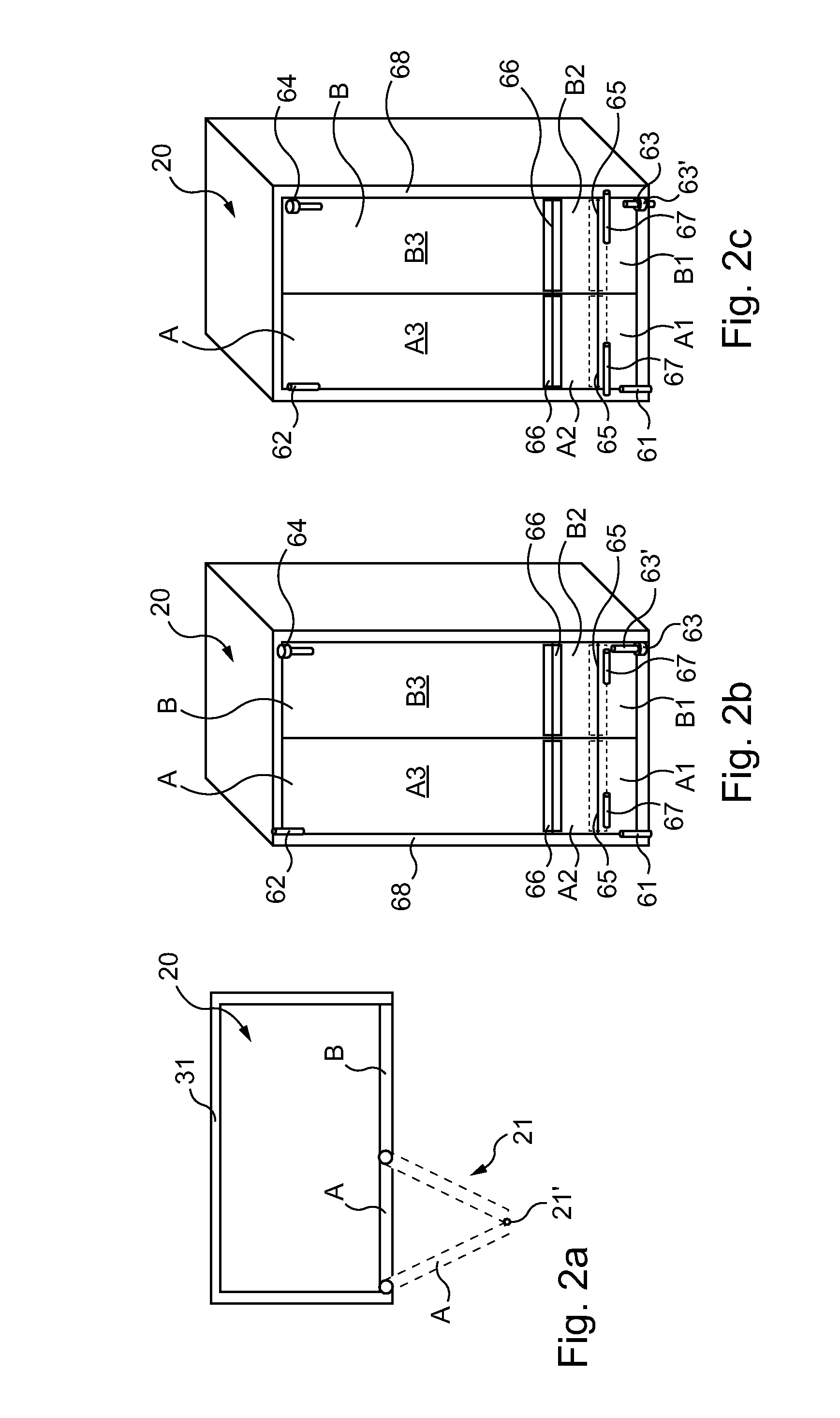
[0168]The toilet area 120 comprises an access door 121 intended, as shown in FIG. 4a, to isolate the toilet area 120 from the rest of the aircraft cabin.
[0169]For this second embodiment, FIGS. 4a, 4b illustrate a toilet area 120 housing only a toilet bowl 122.
[0170]Of course, different pieces of equipment could also be provided as described above in relation to the first embodiment, and in particular a washbasin, a work surface and a cupboard.
[0171]In an evacuation configuration of the toilet area 120, as shown in FIG. 4b, the access door 121 occupies a folded position in the toilet area 120.
[0172]As in the first embodiment, the access door 121 th...
third embodiment
[0189]A description will now be given with reference to FIGS. 5a-5b et seq. of a toilet area 220.
[0190]In this non-limitative example of implementation, the aircraft comprises a conventional cylindrical fuselage, the cabin extending for substantially lengthwise along the axis of the cylindrical fuselage of the aircraft.
[0191]As shown in FIGS. 5a and 5b, an evacuation exit 210 is provided in a side wall 211 of the aircraft. In this type of aircraft, the lateral flank of the fuselage is substantially vertical and opens onto the outside so that an evacuation exit 210 of the cabin can be incorporated into the side wall 211.
[0192]The evacuation exit 210 can be closed by an evacuation door 212.
[0193]Conventionally in this type of aircraft, the evacuation door 212 can be slidably mounted against an external surface of the side wall 211 of the fuselage of the aircraft. The movement of the evacuation door 212 is for example a circular translation movement controlled by an arm on a deformable...
PUM
 Abstract
Description
Claims
Application Information