Microwave heating device

a heating device and microwave technology, applied in microwave heating, electrical/magnetic/electromagnetic heating, electrical apparatus, etc., can solve the problems of non-uniform microwave electromagnetic field distribution and inability to heat uniform microwave objects

Active Publication Date: 2014-06-19
PANASONIC INTELLECTUAL PROPERTY MANAGEMENT CO LTD
View PDF0 Cites 4 Cited by
  • Summary
  • Abstract
  • Description
  • Claims
  • Application Information

AI Technical Summary

Benefits of technology

[0019]With the present invention, there is provided a structure for causing progressive waves being changed in amplitude to pass through the positions where the microwave radiating portions are formed, within the waveguide tube, so that microwaves are dispersedly radiated from the opening portions dispersed at the plurality of positions while the amounts of radiations of the microwaves are changed. This enables provision of a microwave heating device capable of uniform microwave heating of an object to be heated, without using a rotational mechanism.

Problems solved by technology

A non-uniform microwave electromagnetic-field distribution (microwave distribution) within the heating chamber presents a problem in that uniform microwave heating of the object cannot be heated.

Method used


Image

  • Microwave heating device
  • Microwave heating device
  • Microwave heating device

Examples


first embodiment

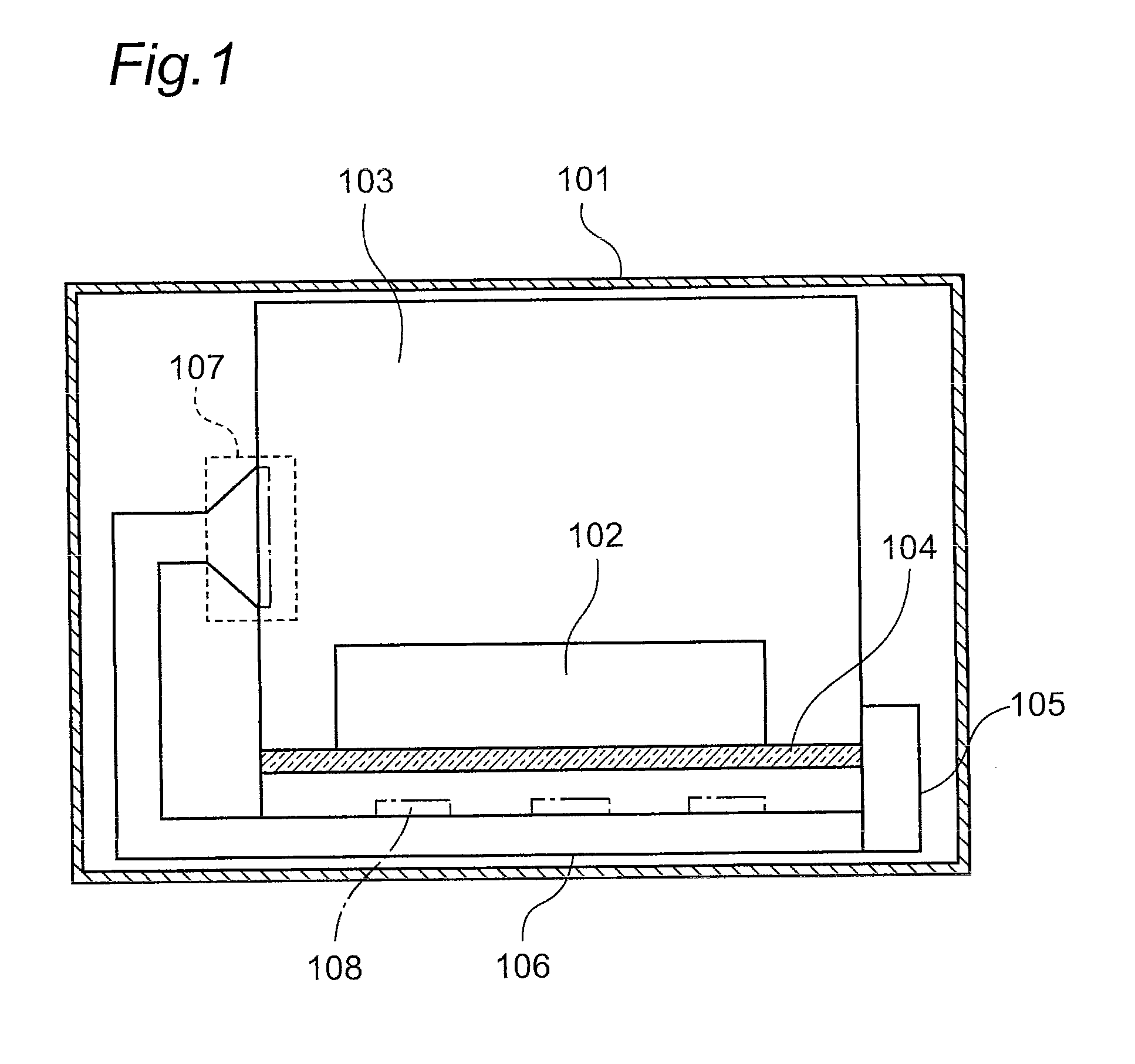
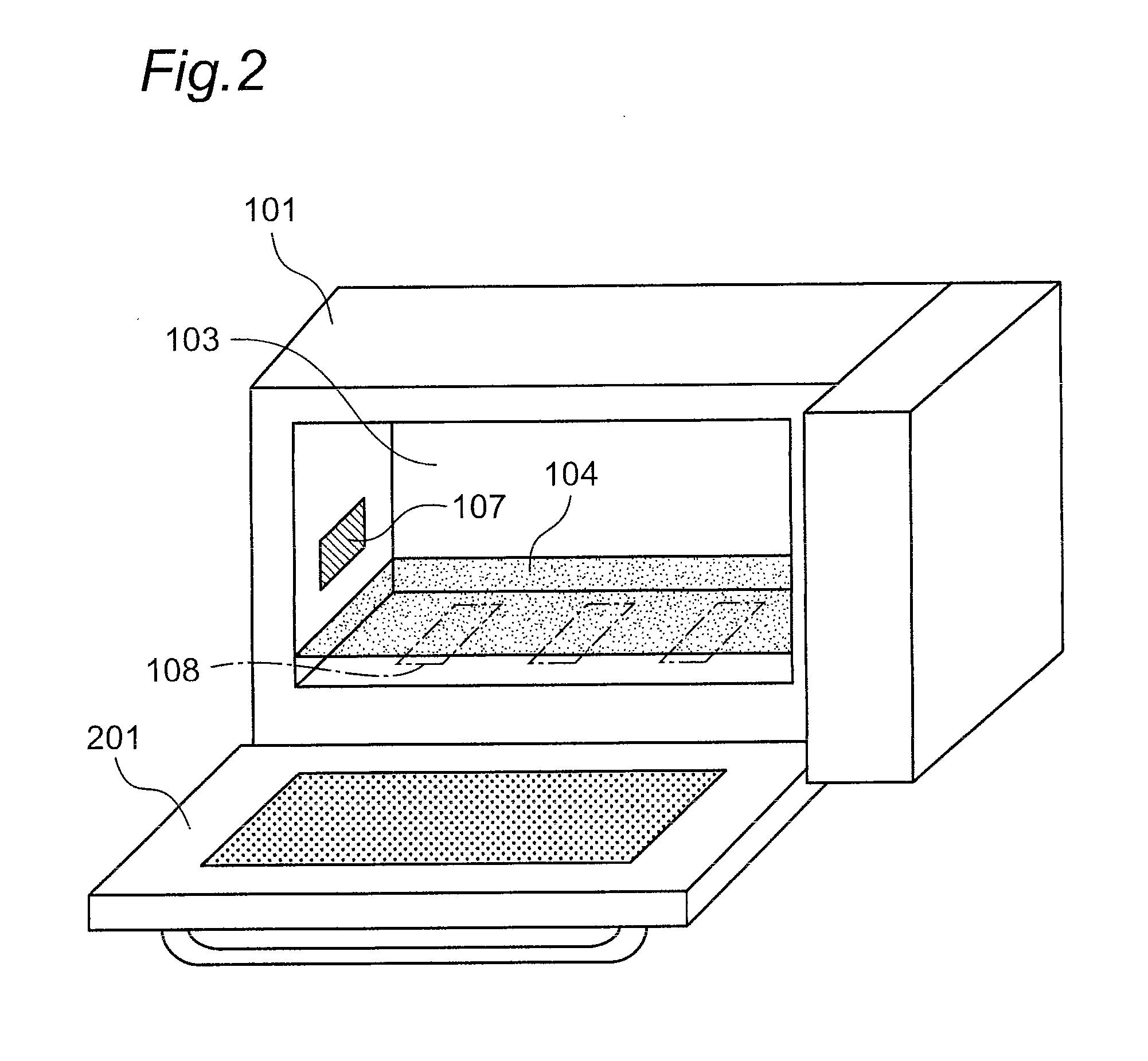
[0048]FIG. 1 is a cross-sectional view schematically illustrating the structure of a microwave oven as a microwave heating device according to a first embodiment of the present invention. Referring to FIG. 1, “101” designates a casing, “102” designates an object to be heated, “103” designates a heating chamber for housing the object 102 to be heated in the chamber, “104” designates a placement portion for placing the object 103 to be heated on the portion, “105” designates a microwave supply portion for supplying microwaves to the heating chamber 103, “106” designates a waveguide tube for propagating, to the heating chamber 103, microwaves supplied from the microwave supply portion 105, “107” designates a heating-chamber input portion extended toward the heating chamber 103 from the termination end of the waveguide tube 106 in the microwave propagation direction, and “108” designates microwave radiating potions for radiating microwaves propagating through the waveguide tube 106, to ...

second embodiment

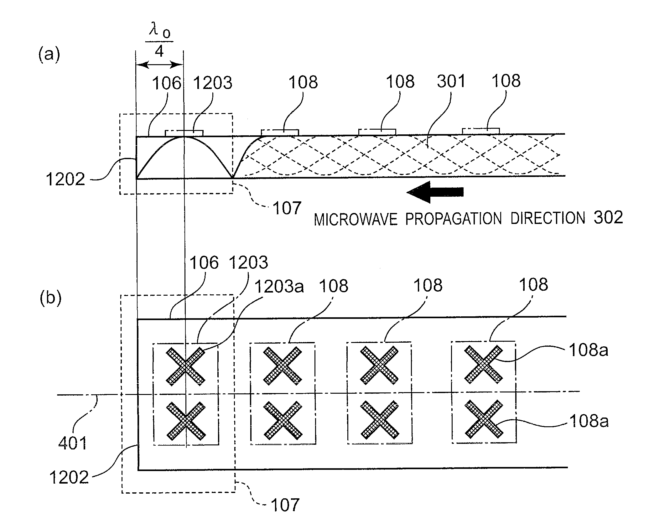
[0061]Hereinafter, a microwave heating device according to a second embodiment of the present invention will be described. The microwave heating device according to the second embodiment is different from the microwave heating device according to the aforementioned first embodiment, in that microwave radiating portions are structured to radiate circularly-polarized waves.

[0062]In the following description about the microwave heating device according to the second embodiment, components having the same functions and structures as those of the components of the microwave heating device according to the first embodiment will be designated by the same reference characters, and the description of the first embodiment will be applied to the detailed description of the second embodiment. Further, fundamental operations according to the second embodiment are similar to the operations according to the aforementioned first embodiment and, therefore, in the following description, different ope...

third embodiment

[0069]Hereinafter, a microwave heating device according to a third embodiment of the present invention will be described. The microwave heating device according to the third embodiment is different from the microwave heating device according to the aforementioned second embodiment, in terms of the structures of microwave radiating portions.

[0070]In the following description about the microwave heating device according to the third embodiment, components having the same functions and structures as those of the components of the microwave heating devices according to the first and second embodiments will be designated by the same reference characters, and the descriptions of the first and second embodiments will be applied to detailed description of the description of the third embodiment. Further, fundamental operations according to the third embodiment are similar to the operations according to the aforementioned first and second embodiments and, therefore, in the following descript...


PUM


Abstract

In a microwave heating device of the present invention, a heating-chamber input portion is adapted to direct, to a heating chamber, microwaves having propagated through a waveguide tube and having passed through the positions where microwave radiating portions are formed, thereby realizing a state where progressive waves are dominant among the microwaves propagating through the waveguide tube, so that the microwave radiating portions are caused to radiate, to the inside of the heating chamber, microwaves based on the progressive waves propagating through the waveguide tube. This enables uniformly heating an object to be heated, without using a rotational mechanism.

Description

TECHNICAL FIELD[0001]The present invention relates to microwave heating devices such as microwave ovens and, more particularly, relates to microwave heating devices having characteristic structures for radiating microwaves to insides of heating chambers.BACKGROUND ART[0002]As representative apparatuses among microwave heating devices for performing heating processing on objects to be heated through microwaves, there are microwave ovens. A microwave oven is adapted to radiate microwaves generated from microwave supply means to the inside of a metal heating chamber, thereby causing an object to be heated within the heating chamber to be subjected to heating processing through radiated microwaves.[0003]Conventional microwave ovens have employed magnetrons as such microwave supply means. Such a magnetron generates microwaves, which are radiated to the inside of the heating chamber from microwave radiating portions through a waveguide tube. A non-uniform microwave electromagnetic-field d...

Claims


Application Information

Patent Timeline
Patent Type & Authority Applications(United States)
IPC IPC(8): H05B6/72
CPCH05B6/708H05B6/70H05B6/72
Inventor SADAHIRA, MASAFUMIHOSOKAWA, DAISUKEYOSHINO, KOJINOBUE, TOMOTAKAOMORI, YOSHIHARU
Owner PANASONIC INTELLECTUAL PROPERTY MANAGEMENT CO LTD
Why Eureka
Try Eureka