System and method for voltage and current sensing

a voltage and current sensing and voltage technology, applied in the field of electrosurgical system and method for operating an electrosurgical generator, can solve the problems of poor overall tolerance control of the transformer, limited surgical use of high permeability materials, and inability to sense signals accurately than desired

Active Publication Date: 2014-06-19
TYCO HEALTHCARE GRP LP
View PDF8 Cites 48 Cited by
  • Summary
  • Abstract
  • Description
  • Claims
  • Application Information

AI Technical Summary

Problems solved by technology

High permeability materials are limited for surgical use since the output of the transformers is non-linear, fluctuates with temperature, and the overall tolerances of the transformers are not well-controlled.
These limitations cause the sensed signals to be less accurate than desired.

Method used


Image

  • System and method for voltage and current sensing
  • System and method for voltage and current sensing
  • System and method for voltage and current sensing

Examples


Embodiment Construction

[0059]Particular embodiments of the present disclosure are described hereinbelow with reference to the accompanying drawings. In the following description, well-known functions or constructions are not described in detail to avoid obscuring the present disclosure in unnecessary detail.

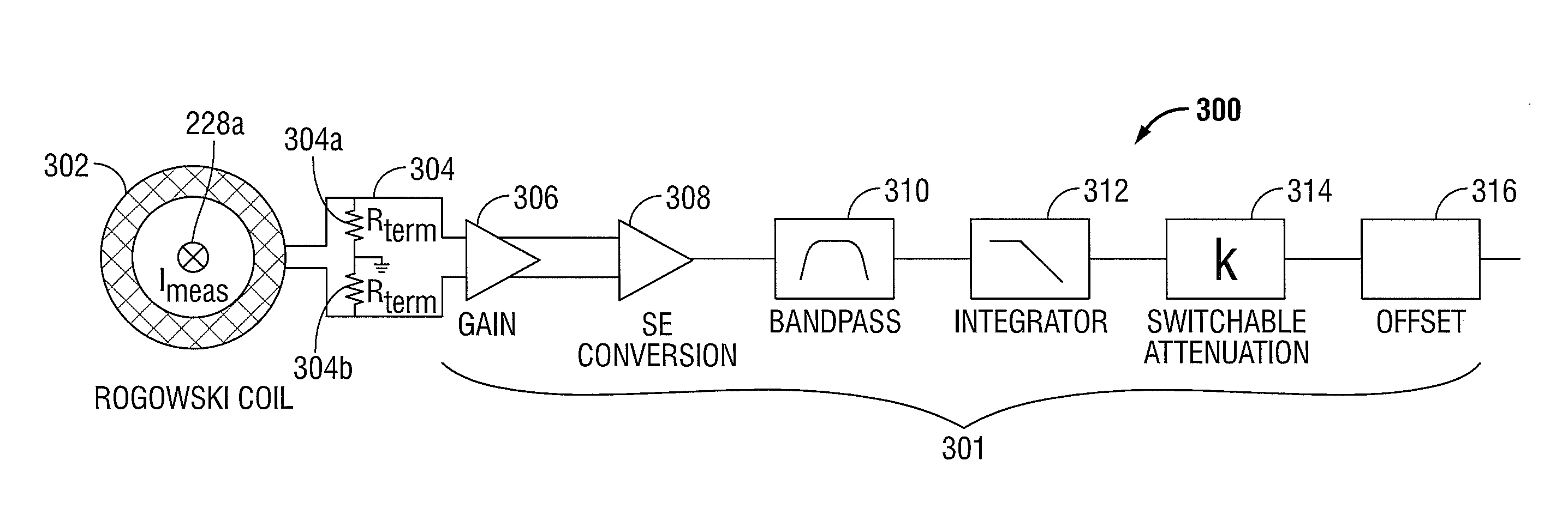
[0060]The present disclosure provides a current sensor configured to measure an AC current of a first conductor. The current sensor includes an outer coil with a first portion and a second portion. Each of the first and second portions form half of a toxoid about the first conductor and the first conductor is disposed through a center of the outer coil. The current sensor includes an inner conductor disposed within the first and second portions of the outer coil, and a conditioning circuit. The conditioning circuit includes a first connector coupled to the first portion of the outer coil and a second connector coupled to the second portion of the outer coil, and the conditioning circuit is configured t...


PUM


Abstract

A current sensor is disclosed. The current sensor includes a Rogowski coil disposed on a flexible printed circuit board with at least one active lead passing through the Rogowski coil.

Description

CROSS REFERENCE TO RELATED APPLICATION[0001]The present application claims the benefit of and priority to U.S. Provisional Application Ser. No. 61 / 738,045, filed on Dec. 17, 2012, the entire contents of which are incorporated herein by reference.BACKGROUND[0002]1. Technical Field[0003]The present disclosure relates to an electrosurgical system and method for operating an electrosurgical generator. More particularly, the present disclosure relates to a system and method for measuring output radio frequency (RF) voltage and current in an electrosurgical generator.[0004]2. Background of Related Art[0005]Electrosurgery involves application of high radio frequency (RF) electrical energy to a surgical site to cut, ablate, or coagulate tissue. During treatment, the surgeon selects the desired tissue effect by setting controls on an electrosurgical generator and brings an electrosurgical instrument (e.g., monopolar, bipolar, etc.) into contact with the surgical site such that the instrument...

Claims


Application Information

Patent Timeline
Patent Type & Authority Applications(United States)
IPC IPC(8): G01R15/18
CPCG01R15/181A61B18/1206A61B18/1402A61B18/1445A61B2018/00827G01R19/28G01R1/20
Inventor GILBERT, JAMES A.
Owner TYCO HEALTHCARE GRP LP
Why Eureka
Try Eureka