Headlight light distribution control device and method

a technology for controlling devices and headlights, applied in the direction of mechanical measuring devices, instruments, and mechanical means, can solve problems such as discomfort of drivers, and achieve the effect of easy control

Active Publication Date: 2014-06-19
DENSO CORP
View PDF4 Cites 29 Cited by
  • Summary
  • Abstract
  • Description
  • Claims
  • Application Information

AI Technical Summary

Benefits of technology

[0020]As a result, because the irradiation direction of the headlight (60) is set to high beam when a predetermined amount of time (beam switching prohibited time Tp) has elapsed after the irradiation direction of the headlight (60) is changed to low beam, long-distance visibility by the driver can be ensured and this is convenient. In addition, because the irradiation direction does not become high beam immediately after the irradiation direction is set to low beam, the driver does not experience discomfort.
[0021]Here, as recited in claim 4, switching of the headlight (60) to high beam can be configured such that, to an actuator (62) configured by a driving section (622) that switches the irradiation direction of the headlight (60) and a drive control section (624) that drives the driving section (622) according to a command from a CPU (22), the beam switching means (244) transmits a control signal for switching the irradiation direction of the headlight (60) to the drive control section (624), and the drive control section (624) switches the irradiation direction of the headlight (60) on the basis of the transmitted control signal. As a result, switching to high beam can be easily controlled by the CPU (22).

Problems solved by technology

Therefore, a problem occurs in that a driver may possibly experience discomfort.

Method used


Image

  • Headlight light distribution control device and method
  • Headlight light distribution control device and method
  • Headlight light distribution control device and method

Examples


Embodiment Construction

[0037]Although an embodiment to which the present invention is applied will be described with reference to the drawings, embodiments of the present invention are not in any way limited by the following embodiment and various embodiments are possible as long as the embodiments belong within the technical scope of the present invention.

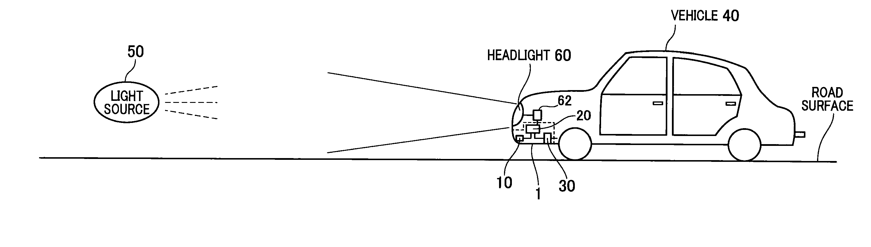
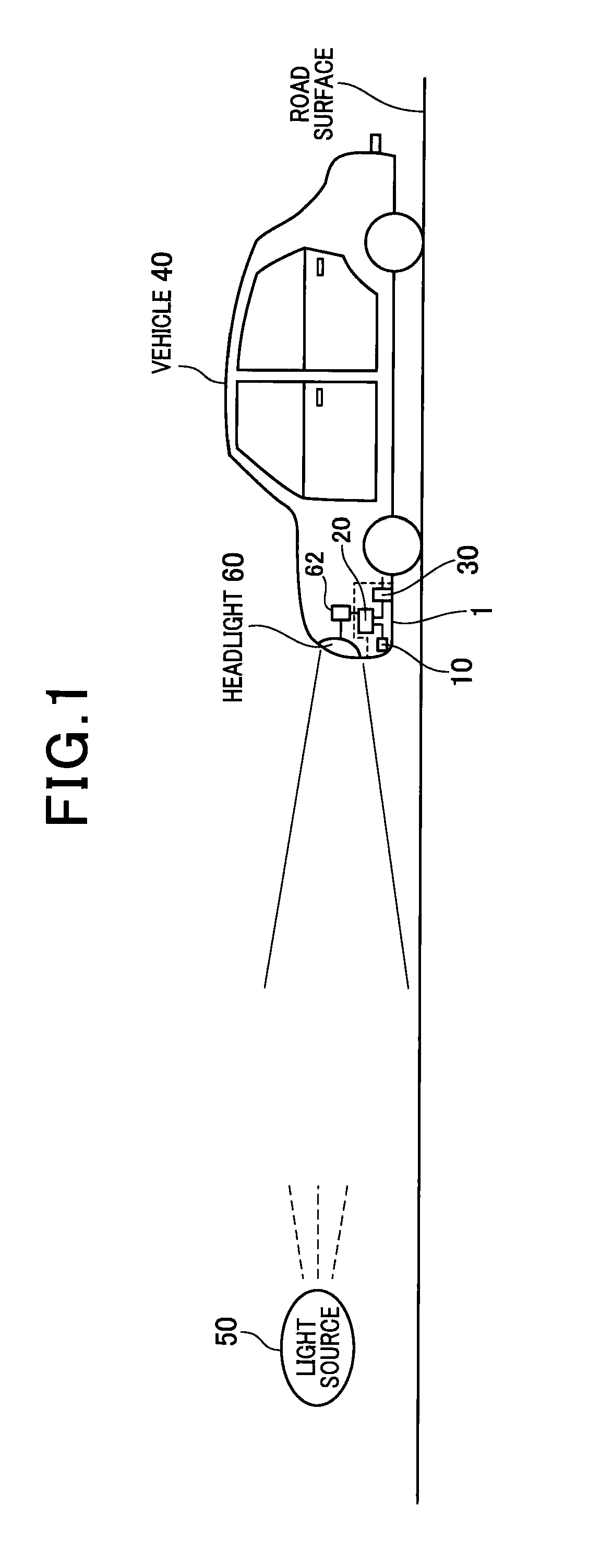
[0038]As shown in FIG. 1, a headlight light distribution control device 1 of the present invention is mounted in a vehicle 40 and has a light source detector 10 that detects whether or not a light source 50 that appears in a region ahead of the vehicle during cruising is present, the light source detector 10 being provided in a front area of the body of the vehicle 40 or inside the vehicle. When the number of times the light source appears within a predetermined amount of time (in other words, the appearance frequency of the light source) detected by the light source detector 10 reaches a predetermined threshold value, a headlight 60 is kept at low beam...


PUM


Abstract

Speed of a vehicle is acquired from a speed detecting device, and then a beam switching threshold, according to the acquired speed, of an irradiation direction of a headlight is initially set. When the number of appearance (i.e. frequency of appearance) of a light source in a predetermined time detected by a light source detection means have become the beam switching threshold or more, the headlight is switched to a low beam. When a predetermined time (beam switching prohibition time Tp) has been passed after the irradiation direction of a headlight was switched to the low beam, the irradiation direction of the headlight is switched to a high beam.

Description

TECHNICAL FIELD[0001]The present invention relates to a headlight light distribution control device that performs switching control of an irradiation direction of a headlight for a vehicle.BACKGROUND ART[0002]Conventionally, there is a device that automatically switches an irradiation direction of a headlight up / down depending on whether or not an oncoming vehicle, a preceding vehicle, or the like is present. The device detects a light source, such as the headlight of an oncoming vehicle or the like, from an image of a region ahead of a vehicle captured by a camera, considers the oncoming vehicle or the like to be present when the light source is detected, and switches the irradiation direction of the headlight of the vehicle (see PATENT DOCUMENT 1).PRIOR ART DOCUMENTSPatent Documents[0003][PATENT DOCUMENT 1] Japanese laid-open patent JP-A-2008-37240SUMMARY OF THE INVENTIONSubject to be Solved by the Invention[0004]However, when the irradiation direction of the headlight of the vehi...

Claims


Application Information

Patent Timeline
Patent Type & Authority Applications(United States)
IPC IPC(8): B60Q1/08
CPCB60Q1/08B60Q1/143B60Q2300/3321B60Q2300/41B60Q2300/112B60Q2300/42B60Q2300/056B60Q1/02B60Q1/1423
Inventor IMAEDA, KOJI
Owner DENSO CORP
Why Eureka
Try Eureka