
Underground transformer electrical fault detection using acoustic sensing technology

a transformer and acoustic sensing technology, applied in the field of underground transformers, can solve problems such as transformer explosion, undesirable electrical faults, overheating electrical,

Inactive Publication Date: 2014-06-19
EATON CORP
View PDF5 Cites 15 Cited by
  • Summary
  • Abstract
  • Description
  • Claims
  • Application Information

AI Technical Summary

Benefits of technology

The disclosed concept is for a system and method to detect electrical faults in an underground transformer unit using acoustic sensing technology. By detecting and analyzing the acoustic signals in the transformer unit, the system can determine if there is an electrical fault and alert about it. This helps to prevent failures and reduce downtime for maintenance.

Problems solved by technology

It is possible, however, that the transformer enclosure is not filled with a fluid media for cooling.
The deterioration of electrical joints, fluid media quality (if present) and / or insulation materials within an underground transformer will often lead to undesirable electrical faults including overheated electrical joints and / or partial discharge.
If these types of electrical faults are not detected and prevented, they could cause major fire hazards and / or transformer explosions.
There is currently no cost effective prior art technology or product for providing continuous (e.g., “24-7” or 24 hours a day, seven days a week) monitoring and detection of electrical faults inside underground transformers.
These technologies, however, are not able to detect overheated electrical joints and / or partial discharge within underground transformers until it is too late.

Method used


Image

  • Underground transformer electrical fault detection using acoustic sensing technology
  • Underground transformer electrical fault detection using acoustic sensing technology
  • Underground transformer electrical fault detection using acoustic sensing technology

Examples


Embodiment Construction

[0012]Directional phrases used herein, such as, for example, left, right, front, back, top, bottom and derivatives thereof, relate to the orientation of the elements shown in the drawings and are not limiting upon the claims unless expressly recited therein.

[0013]As employed herein, the statement that two or more parts are “coupled” together shall mean that the parts are joined together either directly or joined through one or more intermediate parts.

[0014]As employed herein, the term “number” shall mean one or an integer greater than one (i.e., a plurality).

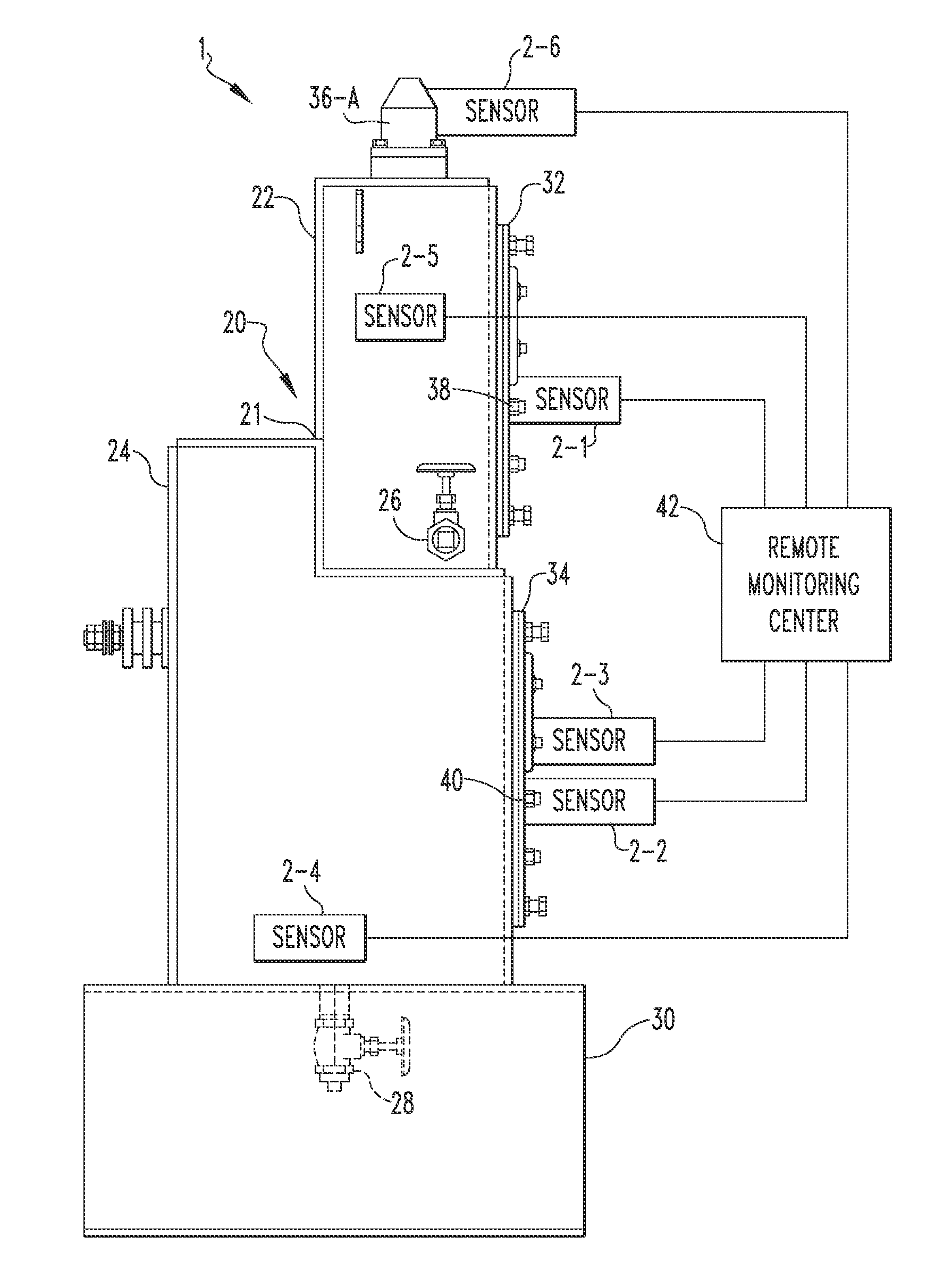
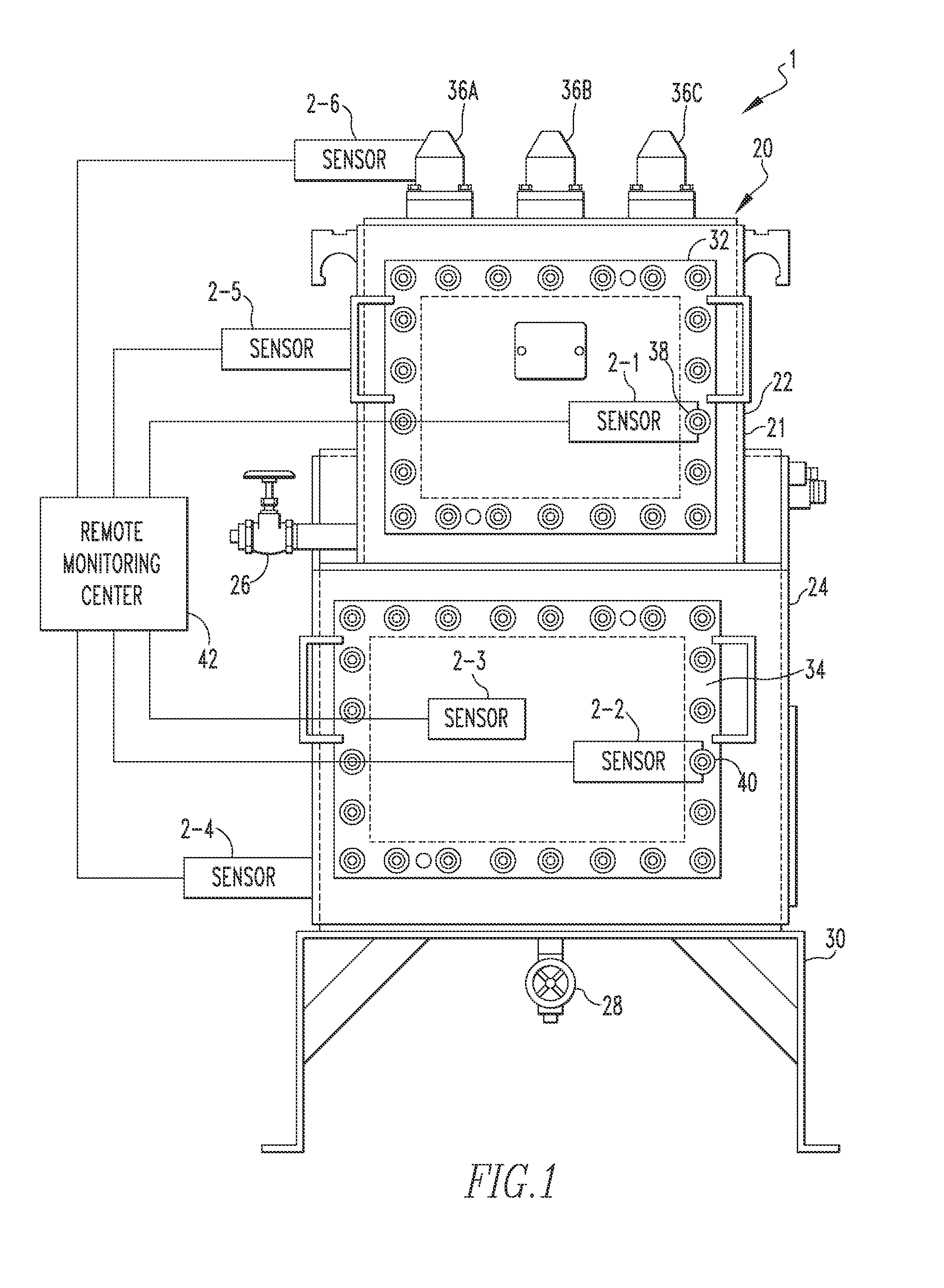
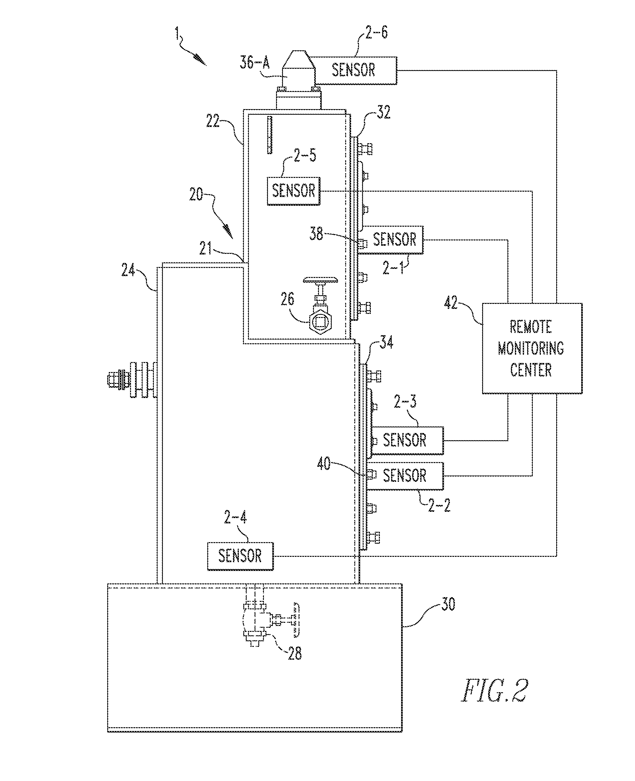
[0015]FIGS. 1 and 2 are schematic diagrams (front and side views, respectively) of a fault detection system 1 according to an exemplary embodiment of the present invention. As seen in FIGS. 1 and 2, fault detection system 1 includes an underground transformer high voltage switch enclosure 20 and, as described in greater detail herein, is configured to detect faults including overheated electrical joints and / or partial discharge ...


PUM


Abstract

An electrical fault detection system includes an underground transformer unit having an enclosure and an electrical busbar element extending from the enclosure, and an acoustic sensor apparatus operatively coupled to an external structure of the enclosure or the electrical busbar element. The acoustic sensor apparatus is structured to: (i) detect an acoustic signal within the enclosure, (ii) analyze the detected acoustic signal and determine whether the detected acoustic signal is indicative of an electrical fault within the enclosure using an event time correlation (ETC) algorithm, and (iii) responsive to determining that the detected acoustic signal is indicative of an electrical fault, output a message indicating that a fault has been detected.

Description

BACKGROUNDField[0001]The disclosed concept relates generally to underground transformers, and, in particular, to a system and method for detecting electrical faults in underground transformers using acoustic sensing technology.Background Information[0002]Underground transformers are used with underground electric power distribution lines at service drops to step down the primary voltage on the line to the lower secondary voltage supplied to utility customers. In general, there are three different types of underground transformers: (i) pad-mount type transformers wherein the transformer enclosure (which houses the actual transformer) is mounted on a pad at ground level and is operated / accessed while standing next to it, (ii) subsurface type transformers wherein the transformer enclosure (which houses the actual transformer) is installed underground and includes a removable top / door so that it can be operated / accessed while standing at ground level next to the open enclosure, and (iii...

Claims


Application Information

Patent Timeline
IPC IPC(8): G01R31/02G06F17/15
CPCG01R31/1209G01R31/1227G01R31/62
Inventor ZHOU, XINFAULKNER, MARK A.MORT, DEBORAH K.WEEKS, JOHN D.
Owner EATON CORP
Learn More