Flying wing with side cargo compartment

Active Publication Date: 2014-06-26
AIRBUS OPERATIONS SAS
View PDF5 Cites 10 Cited by
  • Summary
  • Abstract
  • Description
  • Claims
  • Application Information

AI Technical Summary

Benefits of technology

[0008]One aim of the invention is notably to provide a

Problems solved by technology

However, a simple transposition from an airplane construction to a flying wing results in a flying wing with a large transverse section, which greatly impinges its performance, particularly in the ca

Method used


Image

  • Flying wing with side cargo compartment
  • Flying wing with side cargo compartment
  • Flying wing with side cargo compartment

Examples


Example

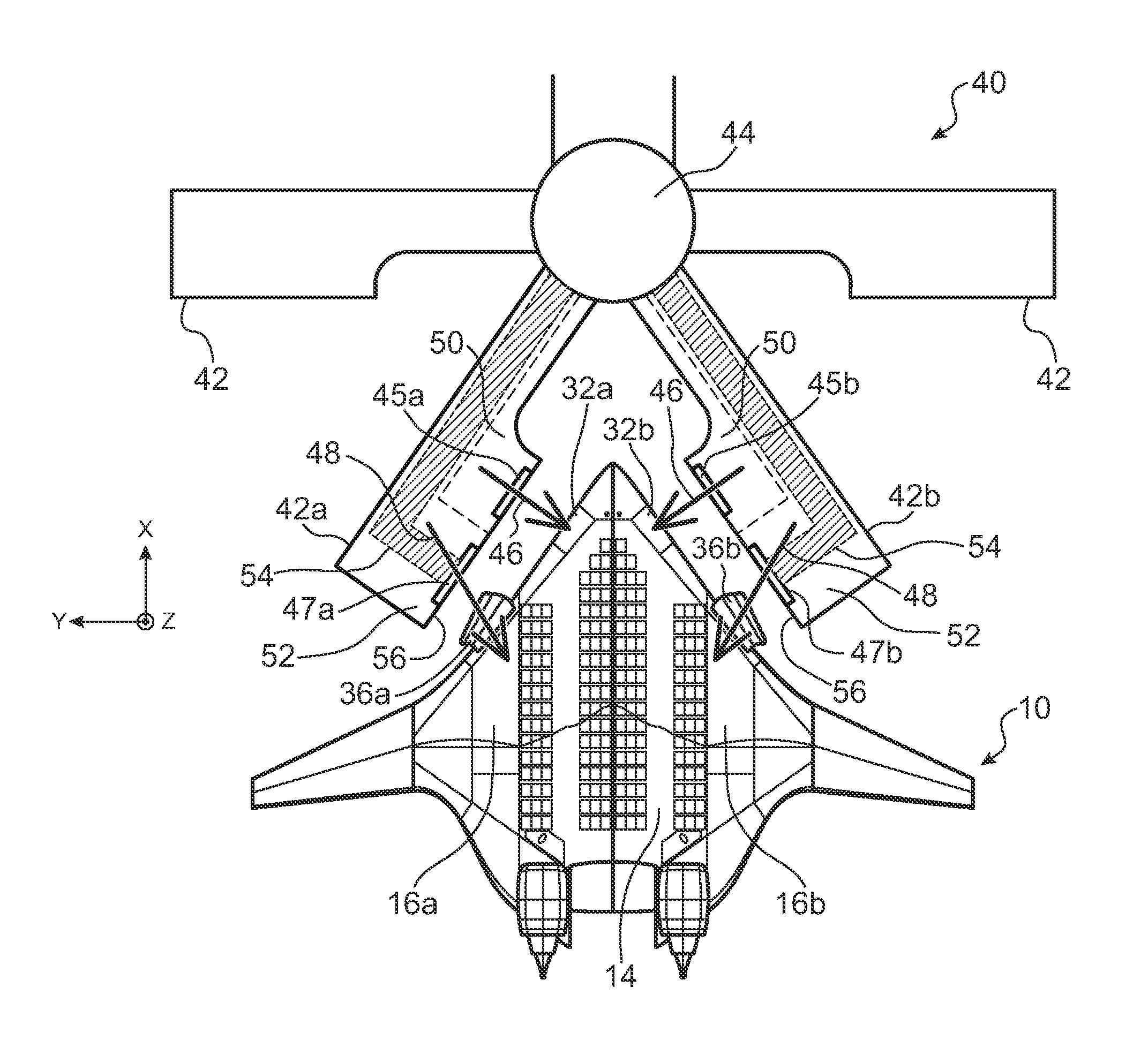
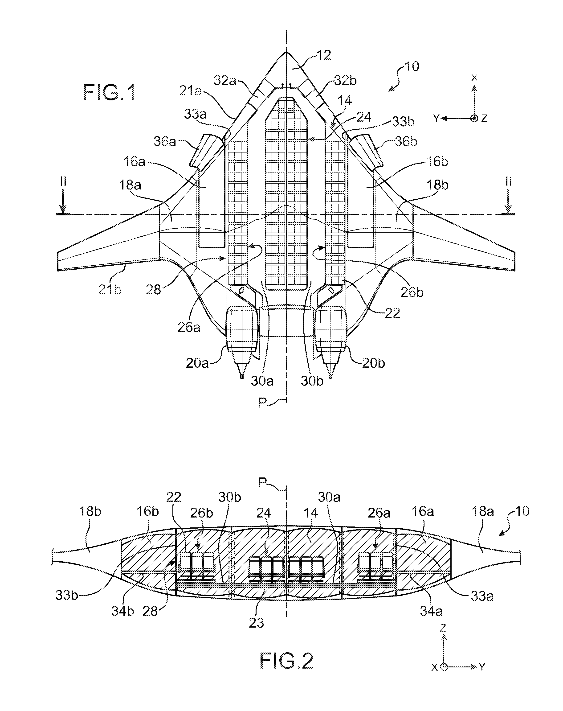
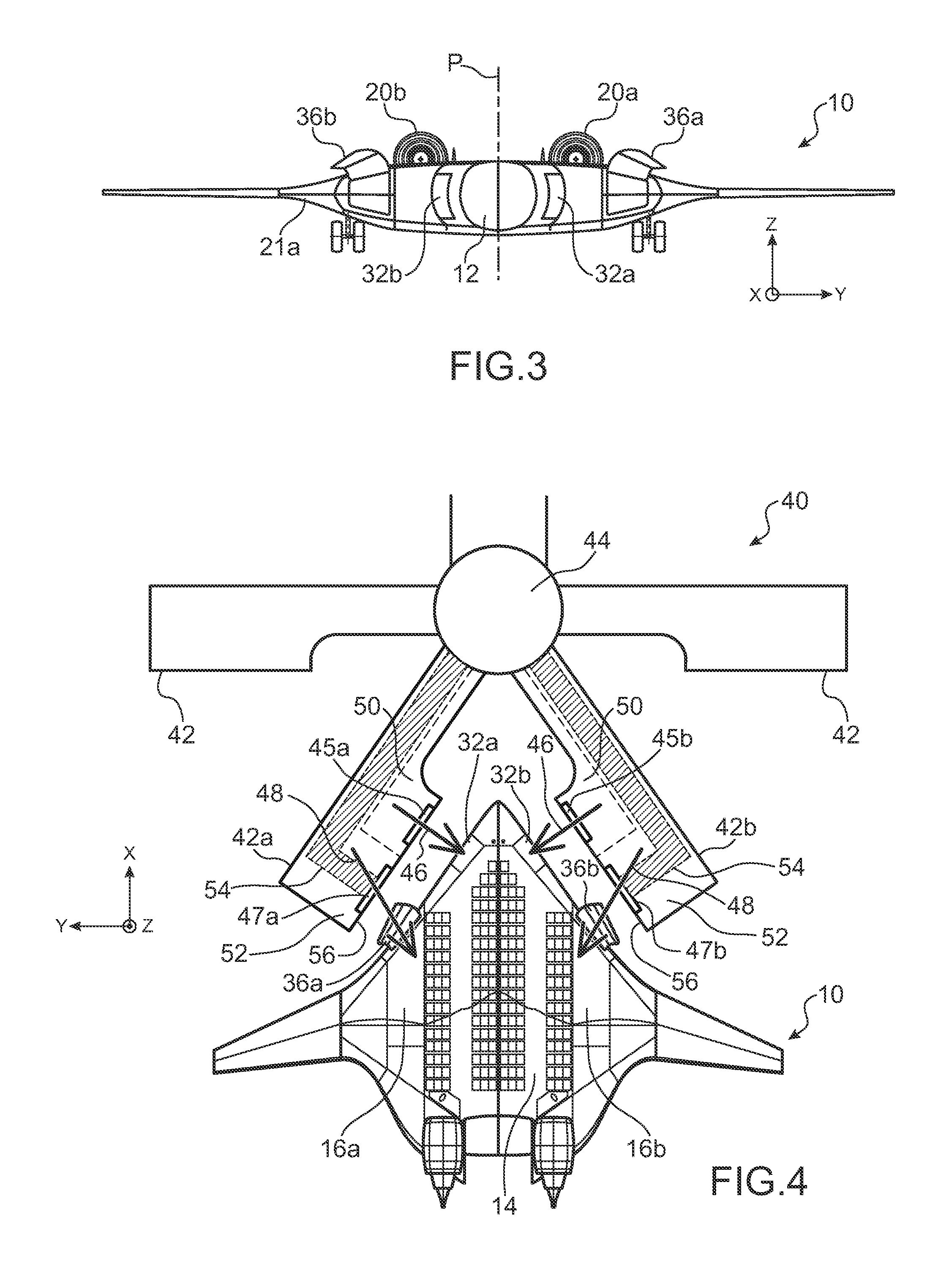
[0039]FIGS. 1 to 3 illustrate a flying wing 10 intended for commercial routes of the short-haul type.

[0040]Throughout this description the longitudinal direction of flying wing 10, i.e., its forward direction, is called X, the vertical direction of flying wing 10, i.e., the direction of height perceived by a passenger on board the flying wing, is called Z, and the transverse direction orthogonal to the longitudinal direction X and vertical direction Z is called Y.

[0041]This flying wing includes a cockpit 12, a passenger cabin 14, and two lateral holds 16a and 16b, together with two fuel tanks 18a and 18b, and two turboshaft engines 20a and 20b positioned to the aft of the flying wing. In addition, flying wing 10 has a leading edge 21a and a trailing edge 21b.

[0042]Cockpit 12 and passenger cabin 14 and lateral holds 16a, 16b jointly define a pressurized space of flying wing 10.

[0043]Passenger cabin 14 includes passenger seats 22 which are resting on a floor 23 (FIG. 2) and which are...


PUM


Abstract

Optimization of the use of the available volume in a flying wing for commercial passenger transport, in particular for short- or medium-haul routes. A flying wing is provided including a passenger cabin together with at least one hold for the transport of luggage and/or goods, in which the hold is positioned laterally relative to said passenger cabin.

Description

CROSS-REFERENCES TO RELATED APPLICATIONS[0001]This application claims the benefit of the French patent application No. 1262802 filed on Dec. 26, 2012, the entire disclosures of which are incorporated herein by way of reference.BACKGROUND OF THE INVENTION[0002]The present invention relates to the field of commercial air passenger transport, in particular over distances corresponding to the fields known as “short-haul” and “medium-haul”.[0003]The invention relates more particularly to a flying wing designed for this purpose, and also an installation for an airport, specially designed for boarding and deplaning of passengers and luggage and / or goods to / from said flying wing.[0004]A flying wing is an aircraft formed entirely of a wing surface, and therefore having no fuselage or empennage. All the moving surfaces used for control are therefore incorporated in the wing surface.[0005]Commercial transport airplanes are habitually constructed by superposing a passenger cabin, firstly, and o...

Claims


Application Information

Patent Timeline
IPC IPC(8): B64D9/00B64F1/32B64D11/06B64F1/30B64C39/10B64C1/14
CPCB64D11/00B64C2001/0036B64C2039/105B64D9/00B64F1/32B64C39/10B64D11/06B64F1/30B64C1/1423B64F1/324B64D9/003
Inventor GALLANT, GUILLAUMEDELAHAYE, ROMAIN
Owner AIRBUS OPERATIONS SAS
Why Eureka
Try Eureka