Optical films for reducing color shift and organic light-emitting display apparatuses employing the same

Active Publication Date: 2014-06-26
SAMSUNG ELECTRONICS CO LTD +2
View PDF3 Cites 15 Cited by
  • Summary
  • Abstract
  • Description
  • Claims
  • Application Information

AI Technical Summary

Benefits of technology

[0010]Provided are optical films for reducing color shift and/o

Problems solved by technology

Furthermore, increased brightness causes reduced pow

Method used


Image

  • Optical films for reducing color shift and organic light-emitting display apparatuses employing the same
  • Optical films for reducing color shift and organic light-emitting display apparatuses employing the same
  • Optical films for reducing color shift and organic light-emitting display apparatuses employing the same

Examples


Example

[0078]Various example embodiments will now be described more fully with reference to the accompanying drawings in which some example embodiments are shown. However, specific structural and functional details disclosed herein are merely representative for purposes of describing example embodiments. Thus, the invention may be embodied in many alternate forms and should not be construed as limited to only example embodiments set forth herein. Therefore, it should be understood that there is no intent to limit example embodiments to the particular forms disclosed, but on the contrary, example embodiments are to cover all modifications, equivalents, and alternatives falling within the scope.

[0079]In the drawings, the thicknesses of layers and regions may be exaggerated for clarity, and like numbers refer to like elements throughout the description of the figures.

[0080]Although the terms first, second, etc. may be used herein to describe various elements, these elements should not be limi...


PUM


Abstract

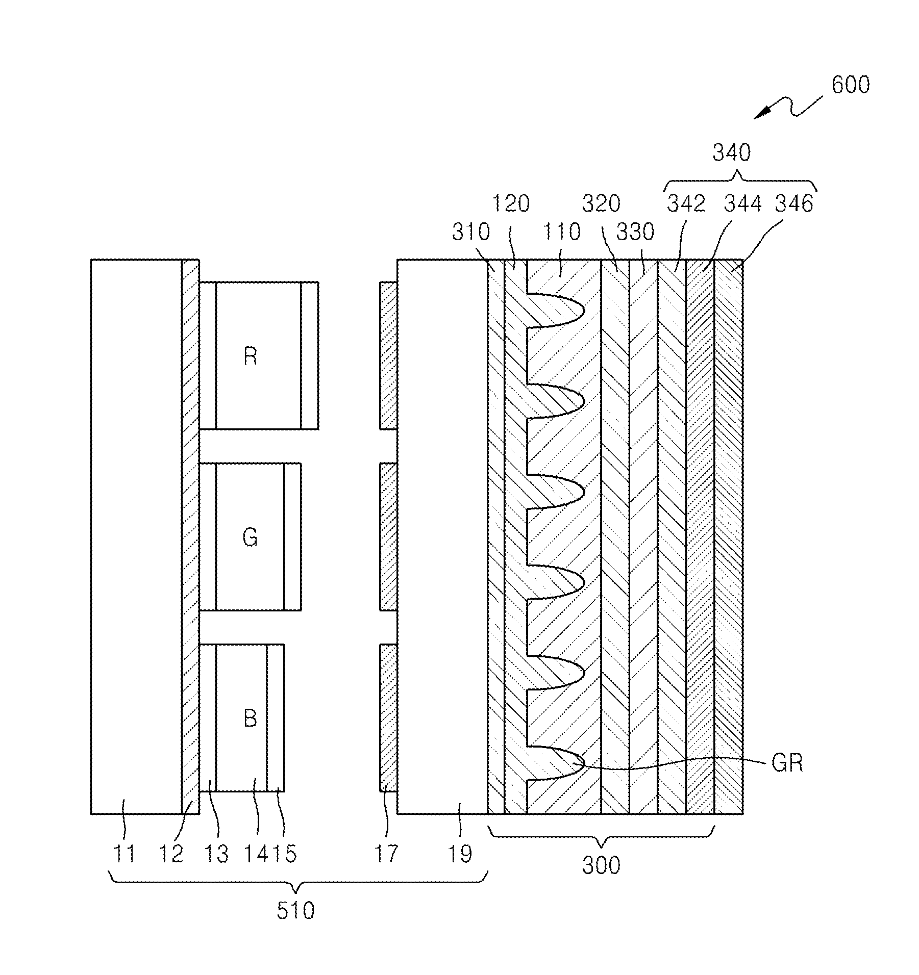
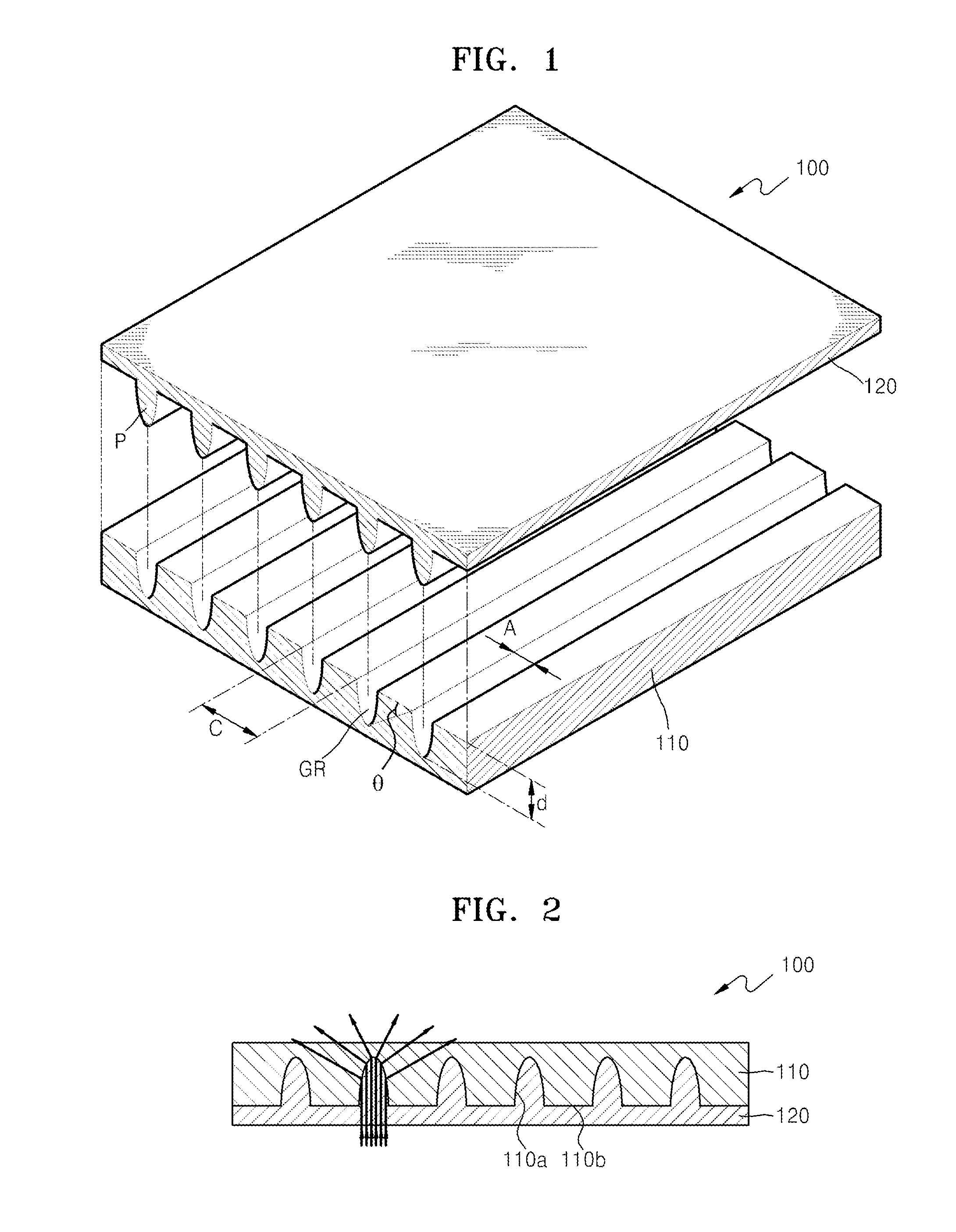
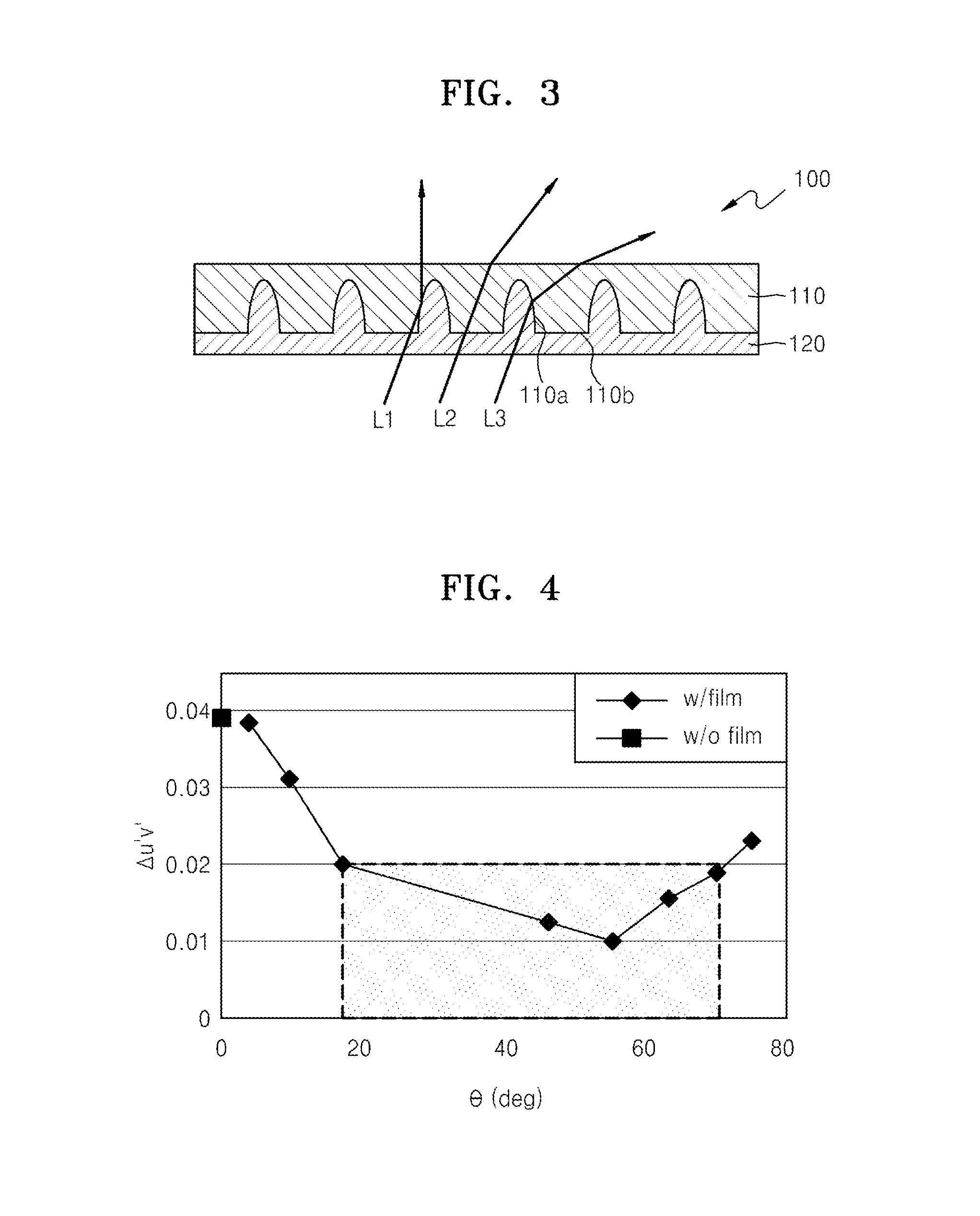
Optical films, and organic light-emitting display apparatuses employing the same, include a high refractive index pattern layer including a first surface and a second surface facing each other, wherein the first surface includes a pattern having a plurality of grooves. The plurality of grooves each have a curved surface and a depth greater than a width thereof. The high refractive index pattern layer is formed of a material having a refractive index greater than 1. The optical films, and the organic light-emitting display apparatuses, further include a low refractive index pattern layer formed of a material having a refractive index smaller than the refractive index of the material constituting the high refractive index pattern layer. The low refractive index pattern layer includes a filling material for filling the plurality of grooves.

Description

CROSS-REFERENCE TO RELATED APPLICATIONS[0001]This application claims the benefit of Korean Patent Applications No. 10-2012-0151338, filed on Dec. 21, 2012, and No. 10-2013-0064967, filed on Jun. 5, 2013, in the Korean Intellectual Property Office, the disclosures of which are incorporated herein by reference in their entirety.BACKGROUND[0002]1. Field[0003]The present disclosure relates to optical films for reducing color shift and / or organic light-emitting display apparatuses employing the same.[0004]2. Description of the Related Art[0005]An organic light-emitting diode (OLED) includes an anode, an organic light-emitting layer, and a cathode. Here, when a voltage is applied between the anode and the cathode, holes are injected from the anode into the organic light-emitting layer, whereas electrons are injected from the cathode into the organic light-emitting layer. At this point, the holes and electrons injected into the organic light-emitting layer are re-combined and generate exci...

Claims


Application Information

Patent Timeline
IPC IPC(8): H01L27/32G02B5/30
CPCG02B5/3025H01L27/322G02B5/0242G02B5/1871H10K59/35H10K59/38H10K50/852H10K50/854H10K50/858H10K50/86H10K50/865G02B5/0247G02B5/0263G02B5/0278G02B27/286
Inventor SHIM, HONG-SHIKJEONG, CHUL-HOCHO, EUN-YOUNGSHIN, YOU-MINKIM, EUI-SOOKIM, HYUN-MINOH, YOUNG
Owner SAMSUNG ELECTRONICS CO LTD
Why Eureka
Try Eureka