Fault protection system and method for fluorescent lamp ballasts

a technology for fluorescent lamps and ballasts, applied in the field of ballasts for fluorescent lamps, can solve the problems of no lamp current conduction in either, no lamp output power, etc., and achieve the effect of mitigate the fault or hazard condition

Inactive Publication Date: 2014-06-26
GENERAL ELECTRIC CO
View PDF10 Cites 10 Cited by
  • Summary
  • Abstract
  • Description
  • Claims
  • Application Information

AI Technical Summary

Benefits of technology

The invention is a lighting circuit that can control the brightness of a fluorescent lamp to a desired level and detect and prevent hazardous or fault conditions. It achieves this by controlling the voltage output by the ballast and can ensure safety and reliability.

Problems solved by technology

Due to safety considerations, regulatory requirements for T5 and smaller diameter fluorescent lamps require that the lamp output power be limited in the case of end of lamp life (EOL) events.
During this condition, the lamp is said to be rectifying and may present a fault or hazard condition due to a high voltage.
However, other fault conditions for a fluorescent lamp may result in no lamp current conduction in either direction, such as when the lamp glass envelope is cracked and the atmosphere of the lamp is lost.

Method used


Image

  • Fault protection system and method for fluorescent lamp ballasts
  • Fault protection system and method for fluorescent lamp ballasts
  • Fault protection system and method for fluorescent lamp ballasts

Examples


Embodiment Construction

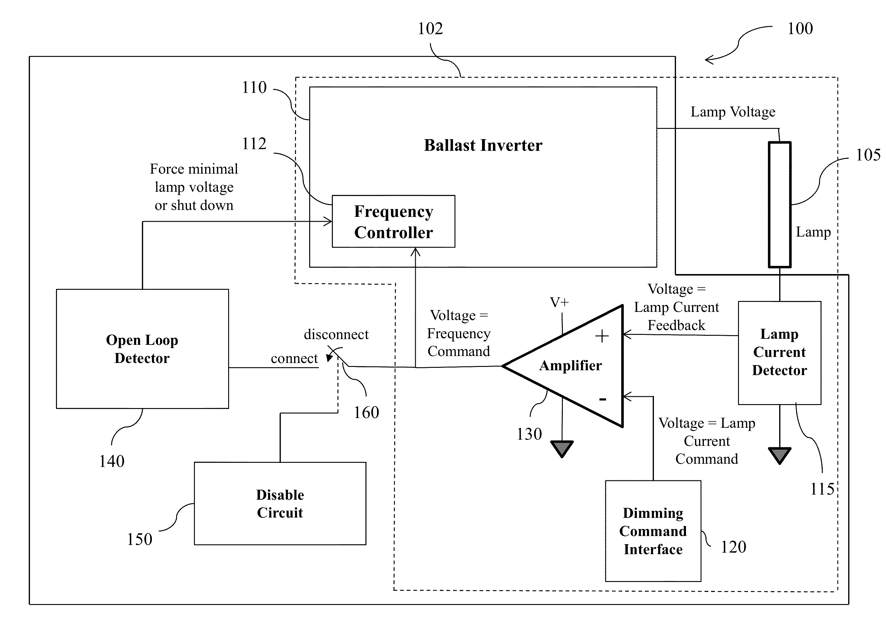
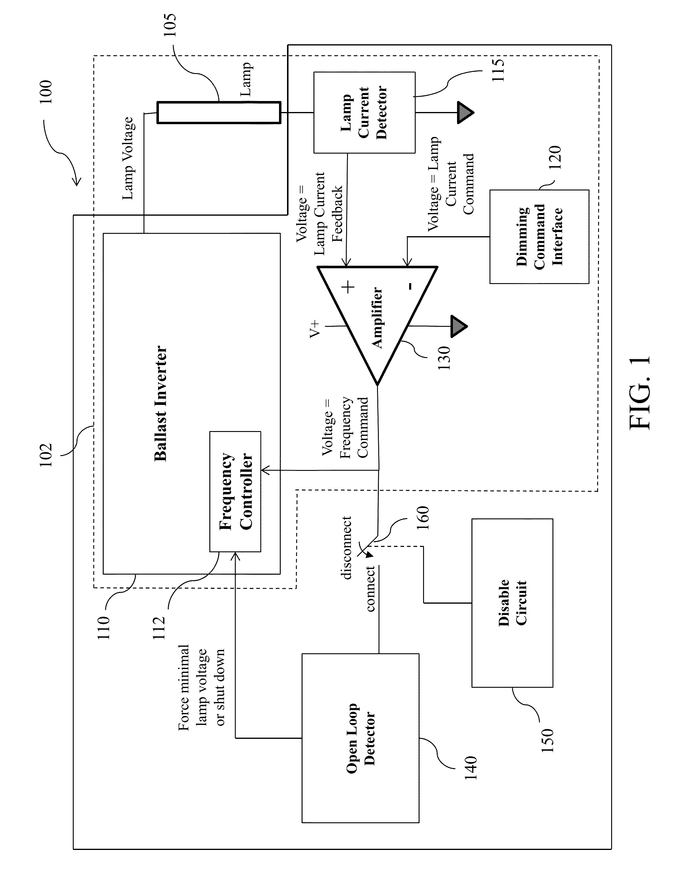
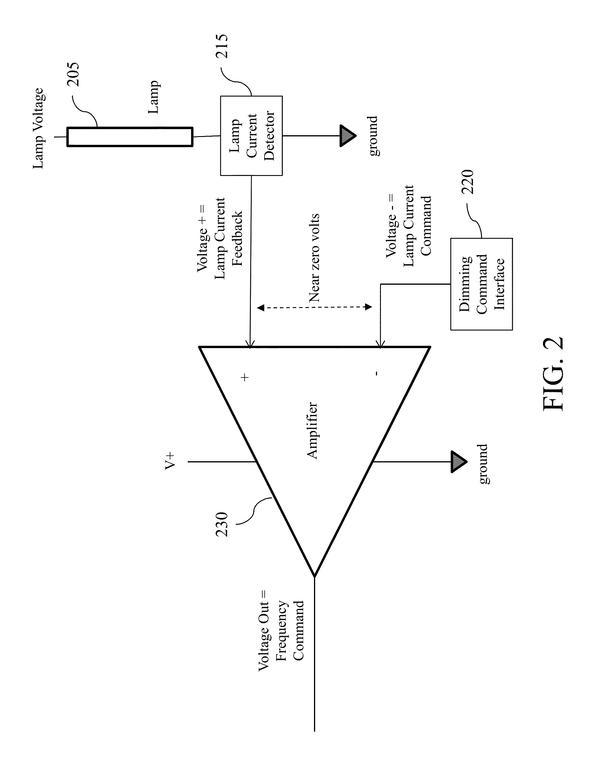
[0005]Embodiments of the present invention provide a lighting system including a ballast inverter in communication with a lamp, a frequency controller, a current detector, a dimming command interface, and an amplifier.

[0006]In the embodiments, the lighting circuit is configured to control the light level, i.e., brightness or dimming, of a fluorescent lamp to a desired level. The desired light level may be, for example, a level desired by a user. The lighting circuit also detects the existence of a fault or hazard condition, and mitigates the fault or hazard condition by forcing the voltage output by the ballast to a safe level or to be cut off.

[0007]In at least one aspect, the embodiments provide a lighting system including a ballast inverter, a summing junction, a current detector, a current command interface, and an open loop detector. The ballast inverter includes a frequency controller and provides a voltage to a lamp. The summing junction is in communication with the ballast in...


PUM


Abstract

Provided is a lighting ballast system and method for fluorescent lamps. The system and method utilize a lamp current control loop to control the light level of a fluorescent lamp. The ballast includes an open loop detector that recognizes an open current control loop as an indication of a fault or hazard condition, and causes the ballast to output a safe lamp voltage or no voltage. The fault or hazard condition may be, for example, a very high voltage at the lamp or very low current across the lamp. The ballast also includes a disable circuit that prevents the open loop detector from triggering at times when the loop is expected to be open such as during ignition and maintenance restarting of the lamp.

Description

I. FIELD OF THE INVENTION [0001]The present invention relates generally to ballasts for fluorescent lamps. More particularly, the present invention relates to ballasts for fluorescent lamps that recognize lamp end of life (EOL) or open circuit conditions.II. BACKGROUND OF THE INVENTION [0002]Due to safety considerations, regulatory requirements for T5 and smaller diameter fluorescent lamps require that the lamp output power be limited in the case of end of lamp life (EOL) events. For example, at EOL one of the lamp filaments may cease to significantly emit electrons thereby causing the lamp to conduct in one direction but not in the opposite direction. During this condition, the lamp is said to be rectifying and may present a fault or hazard condition due to a high voltage.[0003]A known method of providing EOL protection for a rectifying lamp is to include a detection capacitor in series with the lamps, and to sense the direct current (DC) voltage across the detection capacitor. In ...

Claims


Application Information

Patent Timeline
Patent Type & Authority Applications(United States)
IPC IPC(8): H05B37/03
CPCH05B41/2981H05B47/20
Inventor YAO, GANGMIESKOSKI, JAMES DOMENIC
Owner GENERAL ELECTRIC CO
Why Eureka
Try Eureka