Turn lamp for vehicle outside mirror

a technology for turning lamps and vehicles, applied in fixed installation, transportation and packaging, light and heating equipment, etc., can solve the problems of troublesome mounting of two leds, dark area between two leds, etc., and achieve the effect of efficiently entering the light guide lens and preventing the misalignment between the light guide lens and the convex lens

Active Publication Date: 2014-06-26
MURAKAMI CORP
View PDF4 Cites 23 Cited by
  • Summary
  • Abstract
  • Description
  • Claims
  • Application Information

AI Technical Summary

Benefits of technology

[0013]In the present invention, it is possible that: the turn lamp further including a convex lens that converts the light beam emitted from the light source into collimated light; and a part of the collimated light resulting from the conversion enters the light guide lens without being reflected by the reflective surface, and another part of the collimated light is reflected by the reflective surface and enters the light guide lens. Consequently, the light beam emitted from the light source can efficiently enter the light guide lens toward the opposite ends of the light guide lens without diffusing widely. In this case, it is possible that the convex lens is configured in such a manner that the convex lens is integrated with the light guide lens on the back side of the light guide lens using a material that is the same as that of the light guide lens. Consequently, since the light guide lens and the convex lens are integrated with each other, the work of assembling the light guide lens and the convex lens to a turn lamp is facilitated. Also, misalignment between the light guide lens and the convex lens is prevented.
[0014]In the present invention, it is possible that: the light guide lens includes a projection configured in such a manner that the projection is integrated with the light guide lens on the back side of the light guide lens using a material that is the same as that of the light guide lens; the projection includes a first surface allowing the light beam from the light source to enter at a right angle to an optical axis of the light beam, and a second surface arranged in parallel to the reflective surface on a side opposite to the first surface or arranged at a surface that is the same as the reflective surface on the side opposite to the first surface; a part of the light beam that has entered from the first surface enters the light guide lens off the second surface and is guided toward the one end of the light guide lens; and another part of the light beam that has entered from the first surface falls on the second surface, is reflected by the reflective surface, enters the light guide lens and is guided toward the other end of the light guide lens. Consequently, as a result of the light beam entering the light guide lens through the projection, the light beam can efficiently enter the light guide lens. Also, the influence of refraction when the light beam from the light source obliquely enters the light guide lens (body portion of the light guide lens not including the projection) can be reduced.

Problems solved by technology

Also, in the aforementioned structure described in Japanese Patent Laid-Open No. 2010-052566, two LEDs are arranged outward from each other, resulting in the problem of the area between the two LEDs tending to be dark.
In the aforementioned structure described in Japanese Patent Laid-Open No. 2010-052566, it is necessary to mount two LEDs on separate substrates and arrange the LEDs with respective optical axes in directions different from each other, resulting in the problem of taking trouble in the work of mounting two LEDs in separate substrates and the work of assembling the respective substrates to a turn lamp.

Method used


Image

  • Turn lamp for vehicle outside mirror
  • Turn lamp for vehicle outside mirror
  • Turn lamp for vehicle outside mirror

Examples


Embodiment Construction

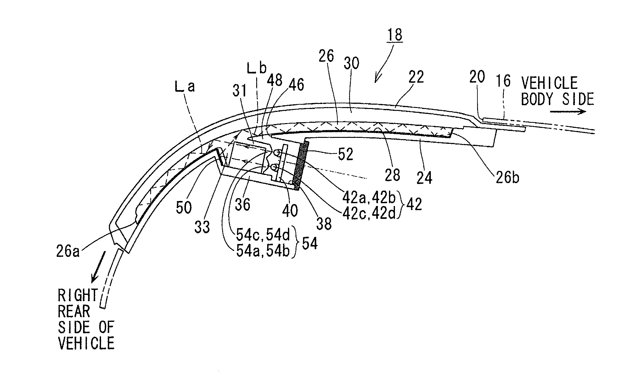
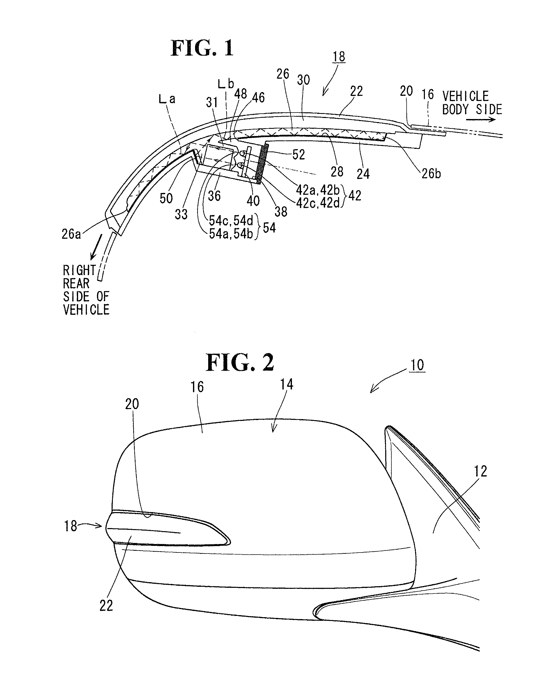
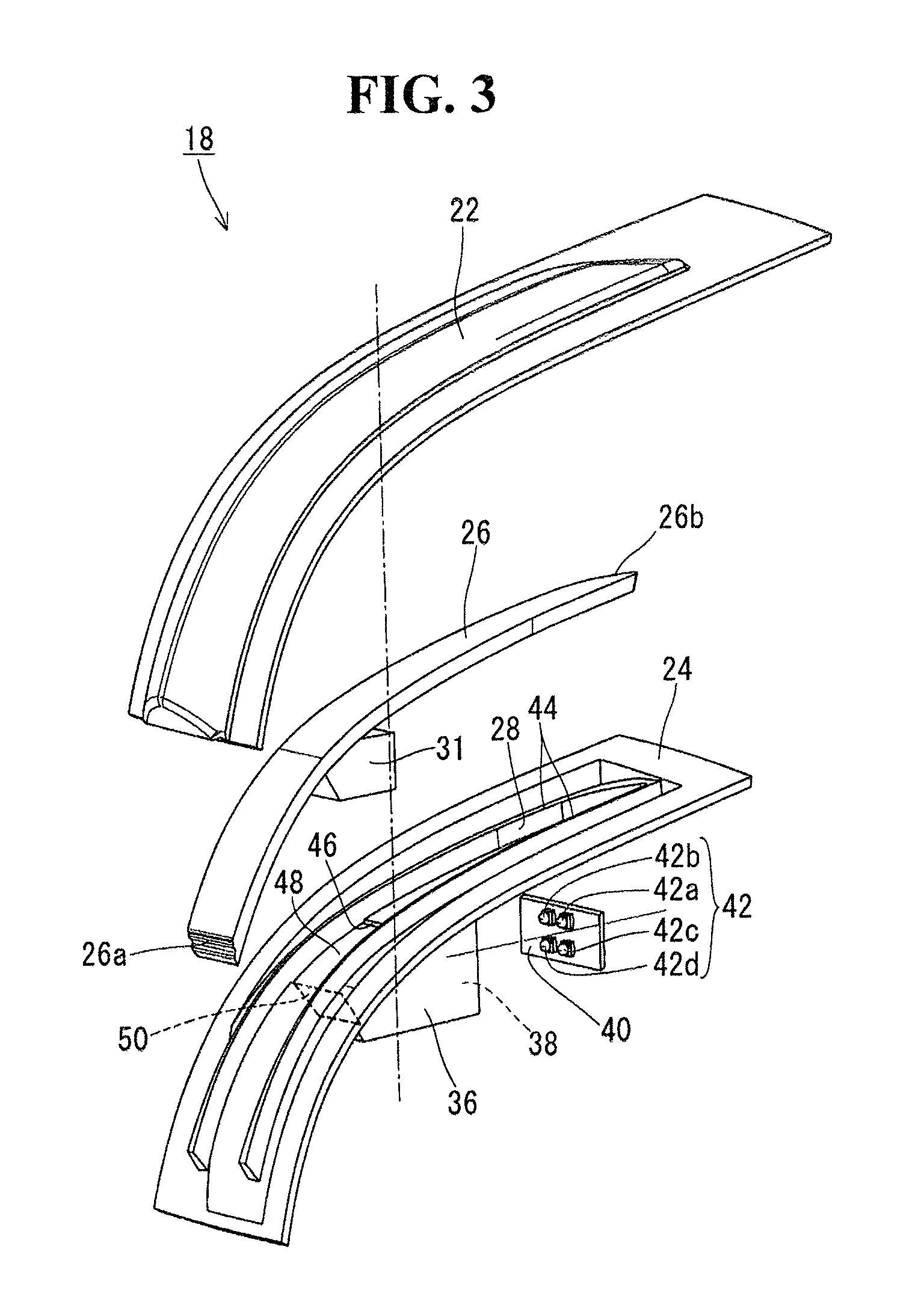
[0023]An embodiment of the present invention will be described below. FIG. 2 illustrates a right-side door mirror 10 equipped with a turn lamp according to the present invention. The door mirror 10 includes a mirror base 12 fixed to a vehicle body (right door) (not illustrated), and a mirror body 14 pivotably attached to and supported by the mirror base 12 so as to be able to move between a used position and a folded position. In the mirror body 14, a frame, a power folding unit and a mirror surface angle adjustment actuator both supported by the frame, a mirror holder supported by the mirror surface angle adjustment actuator in such a manner that a mirror surface angle can be adjusted, a mirror plate fixed to and held by the mirror holder (these are not illustrated), and a turn lamp 18 are arranged and housed inside a mirror housing 16. In the mirror housing 16, a cut portion 20 is formed from a roughly center portion in a width direction of the back side thereof (vehicle front sid...


PUM


Abstract

While a light source is arranged on the back side of a light guide lens, light beams can be emitted from the light source with respective optical axes directed in one direction and be guided toward opposite ends of the light guide lens. A light source and a reflective surface are arranged on the back side of a light guide lens. The light source emits light beams with respective optical axes directed in one direction. One of the light beams obliquely enters the light guide lens toward one end in a long direction of the light guide lens without being reflected by the reflective surface. Another one of the light beams is reflected by the reflective surface and obliquely enters the light guide lens toward another end in the long direction of the light guide lens.

Description

[0001]The disclosure of Japanese Patent Application No. JP2012-281171 filed on Dec. 25, 2012 including the specification, drawings, claims and abstract is incorporated herein by reference in its entirety.BACKGROUND OF THE INVENTION[0002]1. Field of the Invention[0003]The present invention relates to a turn lamp to be assembled to a vehicle outside mirror, which enables light beams from a light source to be emitted with respective optical axes directed in one direction and be guided toward opposite ends of a light guide lens while the light source is arranged on the back side of the light guide lens.[0004]2. Description of the Related Art[0005]As examples of a vehicle door mirror equipped with a turn lamp, there are ones described in Japanese Patent Laid-Open Nos. 2006-114309 and 2010-052566. The turn lamp described in Japanese Patent Laid-Open No. 2006-114309 is one with a light source arranged at an end in a long direction (in other words, long length direction or longitudinal dire...

Claims


Application Information

Patent Timeline
Patent Type & Authority Applications(United States)
IPC IPC(8): F21S8/10
CPCB60Q1/2665B60R1/06B60R1/12B60R1/1207F21S43/19F21S43/14F21S43/27F21S43/26F21S43/239F21S43/241F21S43/245F21S43/249F21S43/37F21S43/33F21S43/40F21S43/30F21S45/10
Inventor ISEKI, KOTANAGANO, HIROAKIINABA, AKIHITO
Owner MURAKAMI CORP
Why Eureka
Try Eureka