Use of additive manufacturing processes in the manufacture of custom orthoses

a technology of additive manufacturing and custom orthoses, applied in the field of custom orthoses manufacturing methods, can solve the problems of labor and time consumption of conventional processes for making custom orthoses, affecting the quality of custom orthoses, and requiring several weeks for conventional processes to achieve the effect of high definition, greater freedom of movement, and strengthening the effect of definition

Active Publication Date: 2014-06-26
3D PATENTS LLC
View PDF1 Cites 31 Cited by
  • Summary
  • Abstract
  • Description
  • Claims
  • Application Information

AI Technical Summary

Benefits of technology

[0017]A customized, form-fitting surface of a custom orthosis may have a contour that is defined by a plurality of adjacent, mutually adhered elements. In various embodiments, the adhered elements have dimensions that impart the finished product with a high degree of definition, including smooth surface contours. Adjacent adhered elements are also permitted to integrate with one another, which eliminates weak points in the finished structure (e.g., discrete boundaries between adjacent elements, etc.) and strengthens it.
[0018]Further customization may be achieved when additive manufacturing processes are used that provide for the use of two or more materials (e.g., different materials; materials with different properties, such as hardness, etc.) to define different regions of each element (e.g., layer, etc.). When such a process is used, one or more layers of a custom orthosis may include one or more rigid regions and one or more flexible regions, thus imparting the custom orthosis with a tailored pattern of rigid and flexible features. Without limiting the scope of this disclosure, rigid features may prevent unnatural motion (e.g., excessive movement beyond a normal range of motion, etc.) while enabling a normal range of motion. More flexible features may provide for greater freedom of movement (e.g., for uninjured anatomical structures, for injured anatomical structures of the body part that are experiencing limited range or motion, etc.).

Problems solved by technology

From the forgoing, it should be apparent that conventional processes for making custom orthoses are labor intensive and time consuming.
Because conventional processes for making custom orthoses (e.g., custom ankle braces, customized portions of knee braces, etc.) may be very labor-intensive, such processes, from casting of a negative mold to completion of the custom orthosis, typically take several weeks (e.g., a month, etc.) to complete.

Method used


Image

  • Use of additive manufacturing processes in the manufacture of custom orthoses
  • Use of additive manufacturing processes in the manufacture of custom orthoses
  • Use of additive manufacturing processes in the manufacture of custom orthoses

Examples


Embodiment Construction

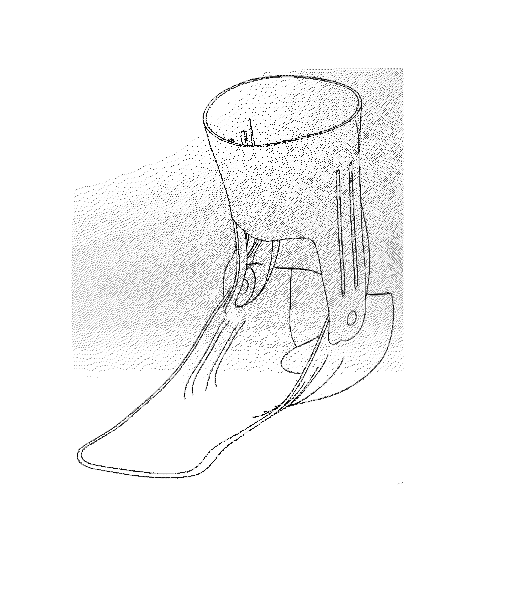
[0033]In various embodiments, processes for making custom orthoses are disclosed and depicted. Although the disclosed embodiments relate to the manufacture of a custom foot bed for an ankle brace, processes that incorporate teachings of this disclosure may also be used to fabricate features of other types of orthoses that are custom-made for use with a body part of a particular individual, and in processes for making entire orthoses.

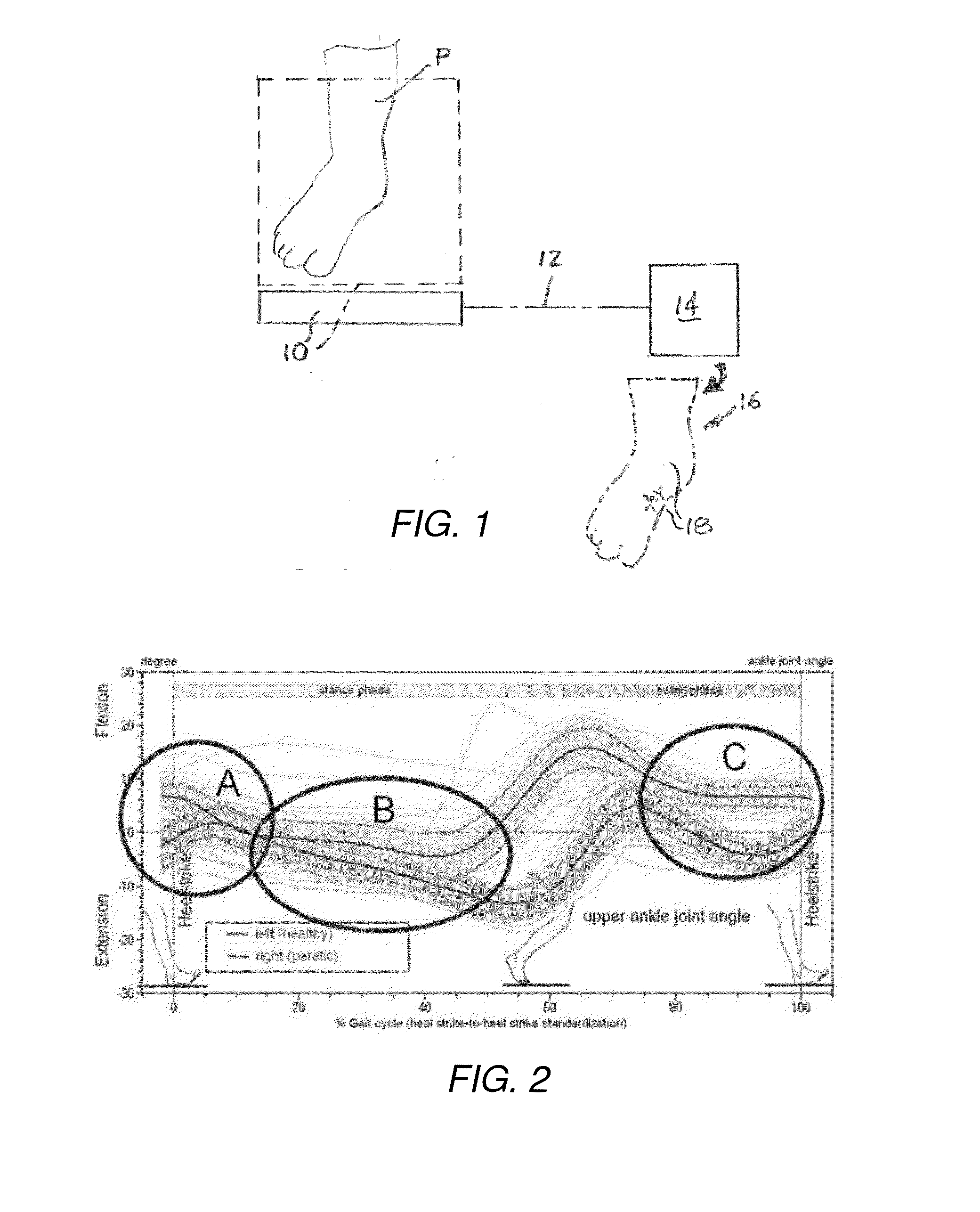
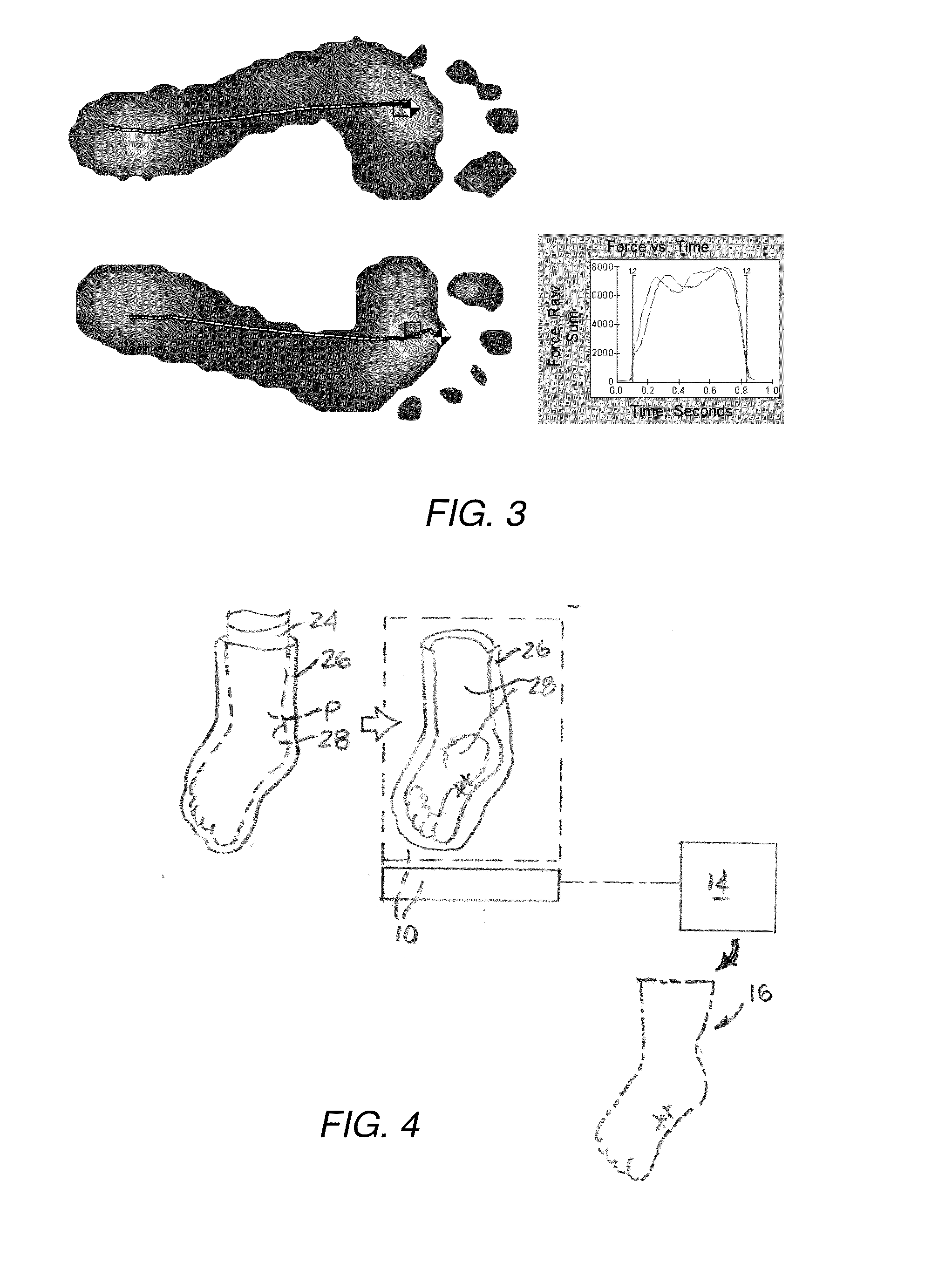
[0034]With reference to FIG. 1, an embodiment of a method for obtaining a negative model of a body part P—depicted as the sole of an individual's foot—is illustrated. In such a method, a scanner 10 that has been configured to generate a three-dimensional representation of a scanned object may be used to generate a three-dimensional digital representation of the body part P. In some embodiments, the scanner 10 may comprise a digitizer that operates based on a so-called “last,” or basic representation (e.g., based on common dimensions for a particular demo...


PUM

PropertyMeasurementUnit
thicknessaaaaaaaaaa
timeaaaaaaaaaa
timeaaaaaaaaaa

Abstract

A method for manufacturing a custom orthosis, such as an ankle brace, includes use of scanning processes. A digital model of a surface may be applied to a digital orthosis model to define a custom digital orthosis model. The digital model and, thus, the custom digital orthosis model may include one or more standard features. The custom digital orthosis model may be used with an automated manufacturing process to make some or all of the custom orthosis. In some embodiments, additive manufacturing processes may be used to form a portion or all of the custom orthosis.

Description

[0001]A claim for priority is hereby made pursuant to 35 U.S.C. §119(e) to the Dec. 22, 2012 filing date of U.S. Provisional Patent Application No. 61 / 745,557, titled USE OF ADDITIVE MANUFACTURING PROCESSES IN THE MANUFACTURE OF CUSTOM ORTHOSES, (“the '557 Provisional Application”) and to the Mar. 15, 2013 filing date of U.S. Provisional Patent Application No. 61 / 800,582, also titled USE OF ADDITIVE MANUFACTURING PROCESSES IN THE MANUFACTURE OF CUSTOM ORTHOSES, (“the '582 Provisional Application”). The entire disclosures of the '557 Provisional Application and the '582 Provisional Application are hereby incorporated herein.TECHNICAL FIELD[0002]This disclosure relates generally to methods for manufacturing custom orthoses, such as ankle braces and, more specifically, to use of additive manufacturing processes to manufacture custom orthoses. In addition, this disclosure relates to systems that employ scanning or digitizing equipment and additive manufacturing equipment in the manufact...

Claims


Application Information

Patent Timeline
Patent Type & Authority Applications(United States)
IPC IPC(8): B29C67/00G06F17/50A61F5/01
CPCB29L2031/7532B29L2031/085B29C64/386A61F5/01B33Y10/00B33Y80/00A61F5/0111Y02P70/50G06F30/00B33Y50/02B29L2031/753G05B19/4097G05B2219/35134G05B2219/49007
Inventor ZACHARIASEN, JOSEPH T.
Owner 3D PATENTS LLC
Why Eureka
Try Eureka