Ophthalmological laser method and apparatus

a laser and ophthalmological technology, applied in the field of femtosecond laser ophthalmological equipment and methods, can solve the problems of irregular flaps, buttonhole flaps (in very steep corneas), free caps (in very flat corneas), and several limitations currently associated with a femtosecond laser system. the overall size of the current femtosecond laser system is much larger than the size of mechanical microkeratome systems

Inactive Publication Date: 2014-06-26
HUANG CHENG HAO
View PDF0 Cites 18 Cited by
  • Summary
  • Abstract
  • Description
  • Claims
  • Application Information

AI Technical Summary

Problems solved by technology

Furthermore, complications such as buttonhole flaps (in very steep corneas), free caps (in very flat corneas) and irregular flaps that are associated with the mechanical microkeratome are rare with the femtosecond laser.
However, several limitations are currently associated with a femtosecond laser system: The overall size of current femtosecond laser systems are much larger than mechanical microkeratome systems.
These two factors negatively impacts patient and surgeon comfort during surgery.
However, there are several disadvantages to this current design.
First, the scanning pattern impinges the scan lens at varying incident angles and requires an extra optical system to continuously maintain beam focal points on the same focal plane.
This creates a more complex, less reliable and potentially more expensive apparatus.
A third disadvantage of this apparatus is that the width of the scanned subarea may vary if the trajectory is not linear.
This limits the trajectories available to the target.
With a constraint on the trajectories available, other possible optical-related applications are limited (especially when a 3D curvature is required inside the cornea or on the lens tissue).
Placing lenses in an optical arm amplifies alignment errors and creates a more complex module.

Method used


Image

  • Ophthalmological laser method and apparatus
  • Ophthalmological laser method and apparatus
  • Ophthalmological laser method and apparatus

Examples


Embodiment Construction

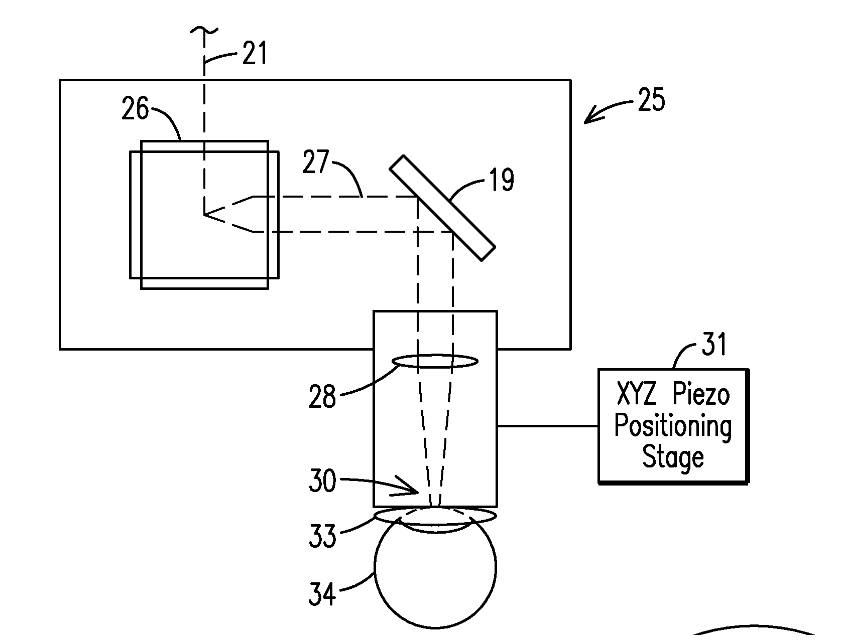
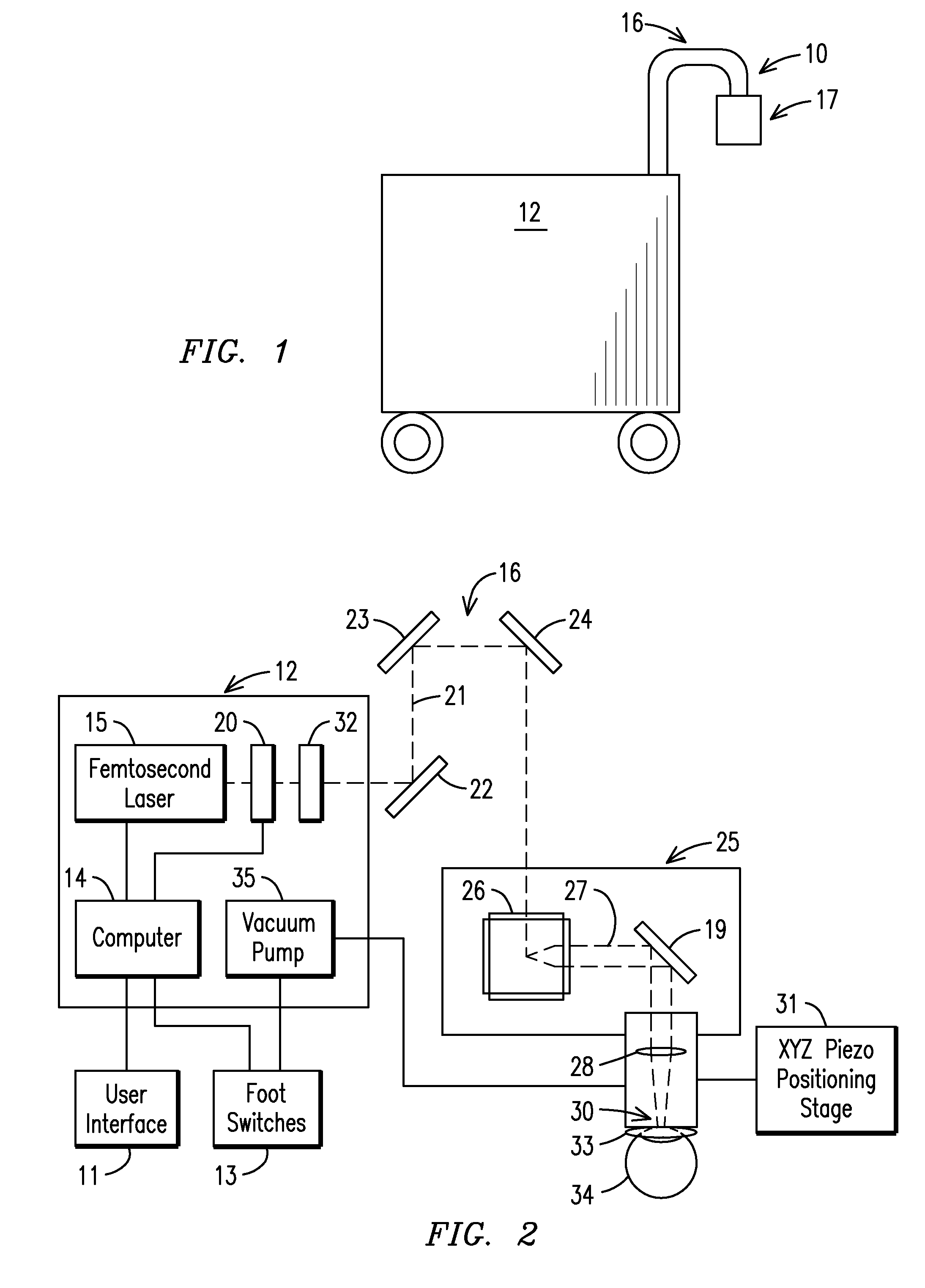
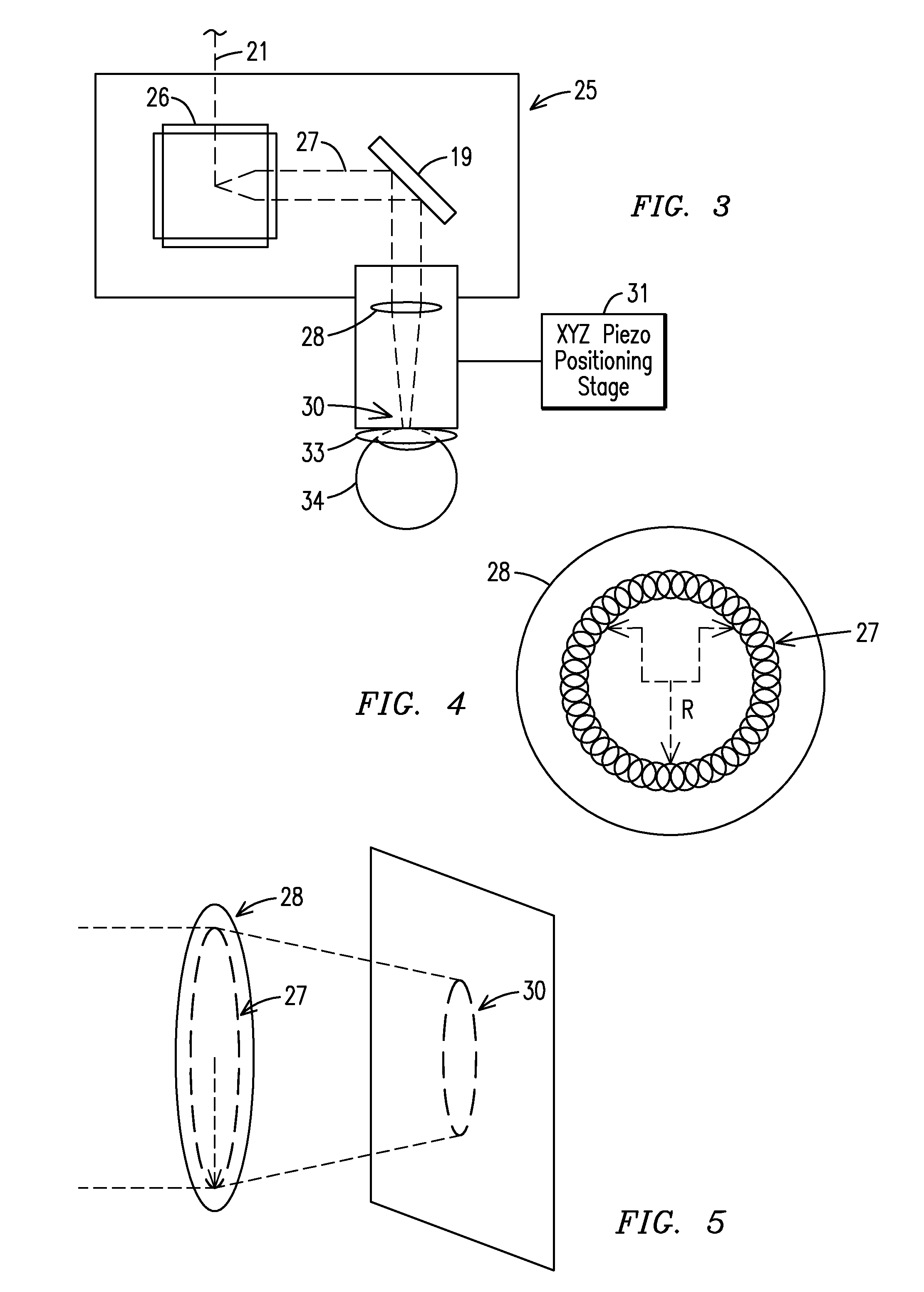
[0016]A laser ophthalmological surgery apparatus 10 in accordance with the present invention in FIGS. 1 and 2 of the drawings includes a user interface 11 connected to a main cabinet 12. A foot switch 13 and the user interface 11 are connected to a computer 14 inside the main cabinet 12. Within the main cabinet 12, laser pulses are generated with a femtosecond laser 15 that is guided through an attached rotating mirror set module 16. The ophthalmological apparatus 10 has a main cabinet 12 and a hand piece module 17 connected to either end of a rotating mirror set module 16. A laser beam expander 20 is positioned in the main cabinet 12 to enlarge the laser beam spot size before it is directed through the rotating mirror set module 16. The laser beam 21 passes through the rotating mirror set module 16 having mirrors 22, 23 and 24, even though it will be understood that more than three mirrors can be used without departing from the spirit and scope of the invention. The laser beam then...


PUM


Abstract

The present invention relates to a femtosecond laser ophthalmological apparatus and method that creates a flap on the cornea for LASIK refractive surgery or for other applications that require removal of corneal and lens tissue at specific locations such as in corneal transplants, stromal tunnels, corneal lenticular extraction and cataract surgery. The femtosecond laser is transferred to a hand piece module via a rotating mirror arm module. In the hand piece, the femtosecond laser beam is scanned into overlapping circles of laser pulses which are then moved in an overlapping trajectory on a patient's eye to ablate the eye tissue in a predetermined pattern.

Description

BACKGROUND OF THE INVENTION[0001]This patent application is a continuation-in-part application of my pending U.S. patent application Ser. No. 13 / 373,591, filed Nov. 22, 2011 for OPHTHALMOLOGICAL LASER METHOD & APPARATUS.[0002]The present invention relates to a femtosecond laser ophthalmological apparatus and method that creates a flap on the cornea for LASIK refractive surgery or for other applications that require removal of corneal and lens tissue at specific locations such as in corneal transplants, stromal tunnels, corneal lenticular extraction and cataract surgery.[0003]The use of an excimer laser to modify the shape of the cornea is called Laser Vision Correction (LVC). Currently the most popular method is called LASIK (Laser-Assisted in-situ Keratomileusis) and accounts for approximately 85% of all LVC preformed. Traditionally, during LASIK, the surgeon uses an instrument called a mechanical microkeratome (physical blade) to create a flap on the cornea. However, over the last...

Claims


Application Information

Patent Timeline
Patent Type & Authority Applications(United States)
IPC IPC(8): A61F9/008
CPCA61F9/00827A61F9/00831A61F9/00836A61F2009/00897A61F2009/00872A61F9/008A61F2009/00887A61F2009/0087
Inventor HUANG, CHENG-HAO
Owner HUANG CHENG HAO
Why Eureka
Try Eureka