
Clips for attaching staples for joining conveyor belt ends, staples for joining conveyor belt ends and clip-staple assemblies

a technology for conveyor belt ends and staples, which is applied in the direction of belt fastenings, v-belt fastenings, belt fastenings, etc., can solve the problems of serious limitations in the field of use of staples, inability to choose metals, and clip liable to stripping, etc., to eliminate such drawbacks, ease of implementation, and robustness in use

Active Publication Date: 2014-07-03
ASER
View PDF4 Cites 9 Cited by
  • Summary
  • Abstract
  • Description
  • Claims
  • Application Information

AI Technical Summary

Benefits of technology

The solution provides robust and versatile clip-staple systems that can withstand diverse directional constraints, particularly in troughing operations, by using average quality metal and reducing thickness for improved bending strength and ease of implementation.

Problems solved by technology

However, this relatively rudimentary means had the disadvantage consisting in that the spikes folded to the outside would make the clip liable to stripping during the operation of the conveyor belt.
The disadvantages presented by the solution of patent FR 2 792 050 consist in the fact that the claws are composed of the same metal as that of the staples, and that therefore it is not possible to choose a metal particularly suited to the clip function, in the fact that the guidance of the spike provided by the raised edge of the lower plate is not perfect, and finally in the fact that the location of the claws is imposed as is the location and orientation of the doors.
The disadvantages seriously limit the fields of use of these staples, in particular with regard to heavy conveyor belts which must often be troughed for transporting bulk materials (coal, lignite, ores, phosphates).
The disadvantages presented by the solution of European patent EP 0 464 399 consists in the fact that it uses round wire clips which have only two branches and that it requires the use of an outer matrix of particular shape which must be perfectly positioned to receive the spikes of the clip branches.
The drawback of round wire clips lies in the fact that in order to have an excellent bending strength, it is necessary to increase the diameter thus causing difficulties resulting from the induced over-thickness which cannot be totally accommodated in a recess of the upper plate of the staple, which created problems with the scrapers.
In addition, the clips made of round wire include branches, the end portions and spikes of which are made by grinding or milling, have mechanical properties which do not differentiate them from the rest of the clips, i.e. the back of the clips and the body of the branches.
However, a small over-thickness which is liable to be hit by the scrapers remains.
If it is desired to increase the diameter of the round wire clip to obtain a better strength therefrom, the problem becomes impossible to solve since it would be necessary to increase the thickness of the upper plate of the staple which can also be hit by the scrapers.

Method used


Image

  • Clips for attaching staples for joining conveyor belt ends, staples for joining conveyor belt ends and clip-staple assemblies
  • Clips for attaching staples for joining conveyor belt ends, staples for joining conveyor belt ends and clip-staple assemblies
  • Clips for attaching staples for joining conveyor belt ends, staples for joining conveyor belt ends and clip-staple assemblies

Examples


Embodiment Construction

[0055]Several preferred embodiments, which are not limitative, showing clips and staples according to the invention will now be described while referring to the figures of the drawing.

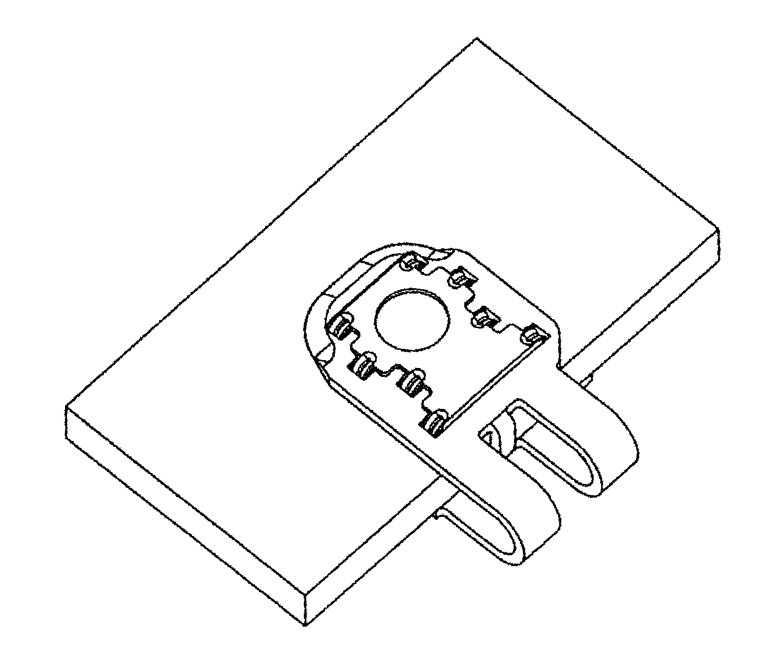
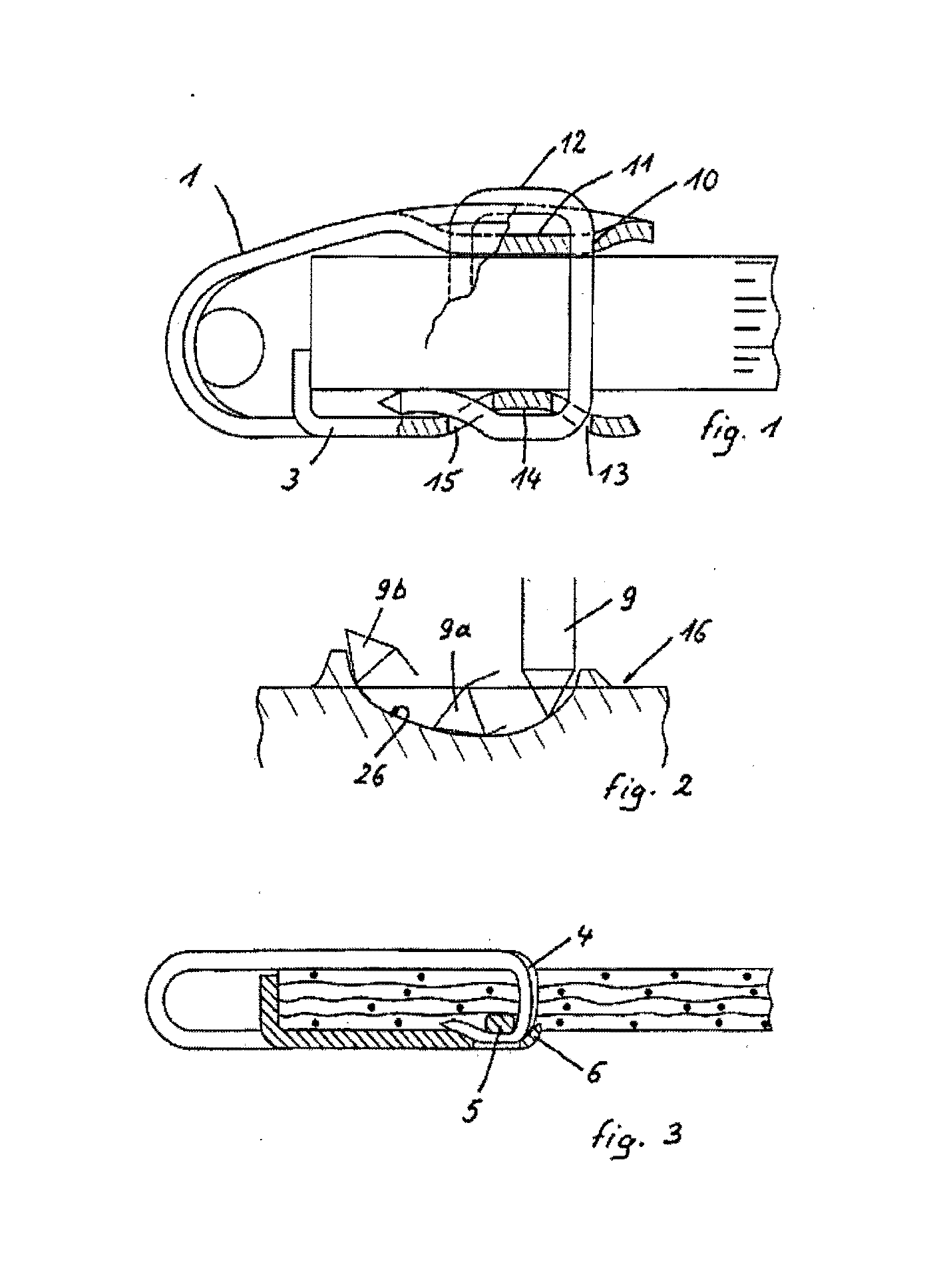
[0056]FIG. 1 is a drawing of a clip / staple system of the prior art according to patent EP 0 464 399 (FIG. 8) mounted on one end of a conveyor belt and shows a clip made of round section metal wire 12, a staple 1 including an upper plate having a recess 11, a lower plate 3 including a bridge 14, holes 10, 13 and 15 being provided for the passage of the branches of the metal wire clip having two generally U-shaped branches.

[0057]FIG. 2 shows in profile the outer matrix 16 which is indispensable for folding the end of a clip branch by virtue of the profile 26, the various phase of the folding being shown in 9, 9a and 9b.

[0058]FIG. 3 represents in longitudinal section a staple according to patent FR 99 045 571 000 (FIG. 8 of this patent), mounted on an end of a conveyor belt. There are shown a claw 4 exte...


PUM


Abstract

A conveyor belt joining staple including upper and lower staple plates situated at different levels joined by knuckles. The upper staple plate has through-holes for passage of staple attaching clip claws and the lower staple plate has bridges that form a recess between a bar of the bridge and an upper surface of the lower plate. The lower staple plate has two shearing lines corresponding to the recess of the bridge, and inlet and outlet toboggans that each have a curved tab. The toboggans are symmetrical with respect to the longitudinal axis of the bridge. Each toboggan has a boss that has an upper round portion and base rounded portions. A portion of the boss is connected to a portion of the tap. Each inlet toboggan-boss is situated in vertical alignment with a corresponding hole of the upper plate for the passage of the clip claws.

Description

CROSS-REFERENCE TO RELATED APPLICATIONS[0001]This is a continuation application of application Ser. No. 12 / 595,496, filed Apr. 21, 2010; which is a National Phase Application of PCT / FR2008 / 000501, filed on Apr. 10, 2008, which claims priority to French Application No. FR 0702650, filed on Apr. 10, 2007, the contents of which are hereby incorporated by reference.FIELD OF THE INVENTION[0002]The present invention relates to clips intended for attaching conveyor belt ends with staples for joining conveyor belt ends. It also relates to improved staples which are particularly suited to gain the best possible benefit from said new clips. Finally, the invention relates to a clip-staple assembly associating both elements prior to the positioning of staples on the conveyor belt ends.BACKGROUND OF THE INVENTION[0003]Joining staples for conveyor belts, belts and similar products composed of an upper plate and a lower plate, both said plates being connected at one end by one or several narrower ...

Claims


Application Information

Patent Timeline
Patent Type & Authority Applications(United States)
IPC IPC(8): F16G3/04
CPCF16G3/04F16G3/02Y10T24/1608Y10T24/1632F16G3/00
Inventor JAKOB, HORST
Owner ASER
Learn More