Illumination method and light-emitting device

a light-emitting device and illumination method technology, applied in the direction of semiconductor devices for light sources, lighting and heating apparatus, and luminescence, can solve the problems of not always achieving favorable color appearance of improving color rendering index scores, not giving sufficient consideration to color appearance, and not actively considering the hunt effect, etc., to achieve the effect of a clearer and more readily seen view

Active Publication Date: 2014-07-03
CITIZEN ELECTRONICS CO LTD
View PDF0 Cites 26 Cited by
  • Summary
  • Abstract
  • Description
  • Claims
  • Application Information

AI Technical Summary

Benefits of technology

[0059]Advantageous effects achieved by the present invention can be more specifically exemplified as follows.
[0060]First, when illuminating with the illumination method according to the present invention or illuminating by a light-emitting device according to the present invention such as a light source, a fixture, or a system, compared to cases where illumination is performed with experimental reference light or experimental pseudo-reference light, white appears whiter, more natural, and more comfortable even at an approximately similar CCT and / or an approximately similar illuminance. Furthermore, differences in lightness among achromatic colors such as white, gray, and black become more visible. As a result, for example, black letters or the like on an ordinary sheet of white paper become more legible. Moreover, while details will be given later, such an effect is completely unexpected in the context of conventional wisdom.
[0061]Second, with illuminance when illuminating with the illumination method according to the present invention or illuminance that is realized by a light-emitting device according to the present invention, a truly natural color appearance as though viewed under several tens of thousands of lx such as under outdoor illuminance on a sunny day is achieved for a majority of colors such as purple, bluish purple, blue, greenish blue, green, yellowish green, yellow, reddish yellow, red, and reddish purple, and in some cases, all colors even in an ordinary indoor environment of around several thousand lx to several hundred lx. In addition, the skin colors of subjects (Japanese), various foods, clothing, wooden colors, and the like which have intermediate chroma also acquire a natural color appearance which many of the subjects feel more favorable.
[0062]Third, when illuminating with the illumination method according to the present invention or illuminating by a light-emitting device according to the present invention, colors among close hues can be identified more easily and work or the like can be performed as comfortably as though under a high-illuminance environment as compared to cases where illumination is performed with experimental reference light or experimental pseudo-reference light even at an approximately similar CCT and / or an approximately similar illuminance. Furthermore, specifically, for example, a plurality of lipsticks with similar red colors can be more readily distinguished from each other.
[0063]Fourth, when illuminating with the illumination method according to the present invention or illuminating by a light source, a fixture, or a system according to the present invention, objects can be viewed more clearly and readily as though viewed under a high-illuminance environment as compared to cases where illumination is performed with experimental reference light or experimental pseudo-reference light even at an approximately similar CCT and / or an approximately similar illuminance.

Problems solved by technology

However, many have pointed out that such light-emitting devices aiming for higher efficiency do not give sufficient consideration to color appearance.
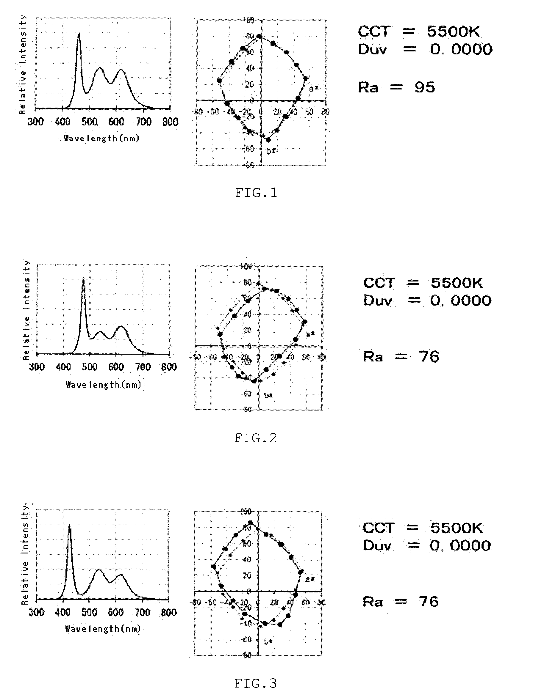
However, recent studies have made it increasingly clear that a high average color rendering index (Ra) or a high special color rendering index (Ri (where i ranges from 1 to 14 or, in Japan, ranges from 1 to 15 pursuant to JIS) does not necessarily lead to favorable color perception in a person.
In other words, there is a problem that the aforementioned methods for improving color rendering index scores do not always achieve favorable color appearance.
Despite having a significant effect on color rendering property, as things stand, the Hunt effect is not actively considered for overall evaluation of a light-emitting device such as a light source, a fixture, or a system.
In addition, while the simplest way to compensate for the Hunt effect is to dramatically increase indoor illuminance, this causes an unnecessary increase in energy consumption.
Meanwhile, with light having its spectrum adjusted so as to, for example, increase chroma of red to be used for special illumination in restaurants or for food illumination, there is a problem that hue (angle) deviation increases in comparison to reference light as evidenced by yellow appearing reddish or blue appearing greenish.
In other words, the color appearance of colors other than a specific color of an illuminated object becomes unnatural.
Another problem is that when a white object is illuminated by such light, the white object itself appears colored and is no longer perceived as being white.

Method used


Image

  • Illumination method and light-emitting device
  • Illumination method and light-emitting device
  • Illumination method and light-emitting device

Examples


first embodiment

[0107]Moreover, an illumination method according to the present invention specifies the invention based on light at a position where an object is illuminated in a case where light emitted from a light-emitting device used in the illumination method illuminates the object. Therefore, illumination methods used by light-emitting devices capable of emitting light at a “position where an object is illuminated” which meets requirements of the present invention are to be included in the spirit and scope of the present invention.

[0108]In addition, an illuminating device according to second and third embodiments of the present invention specify the invention based on light in a “main radiant direction” among light emitted from a light-emitting device. Therefore, light-emitting devices capable of radiating light including light in a “main radiant direction” which meets requirements of the present invention are to be included in the spirit and scope of the present invention.

[0109]As used herei...

second embodiment

[0249]Meanwhile, with the light-emitting device according to the present invention, it was shown that in order to obtain such perceptions, the indices Acg described in Tables 2 to 7 must be within appropriate ranges in addition to Duv. In addition, it was revealed that the various indices, namely, the luminous efficacy of radiation K (lm / W), |Δhn|,

∑n=115ΔCn15,[Expression25]

ΔCn, and (|ΔCmax−ΔCmin|) are favorably within appropriate ranges.

[0250]Firstly, results of the test lights judged to be favorable in the visual experiments revealed the following with respect to Duv and the index Acg.

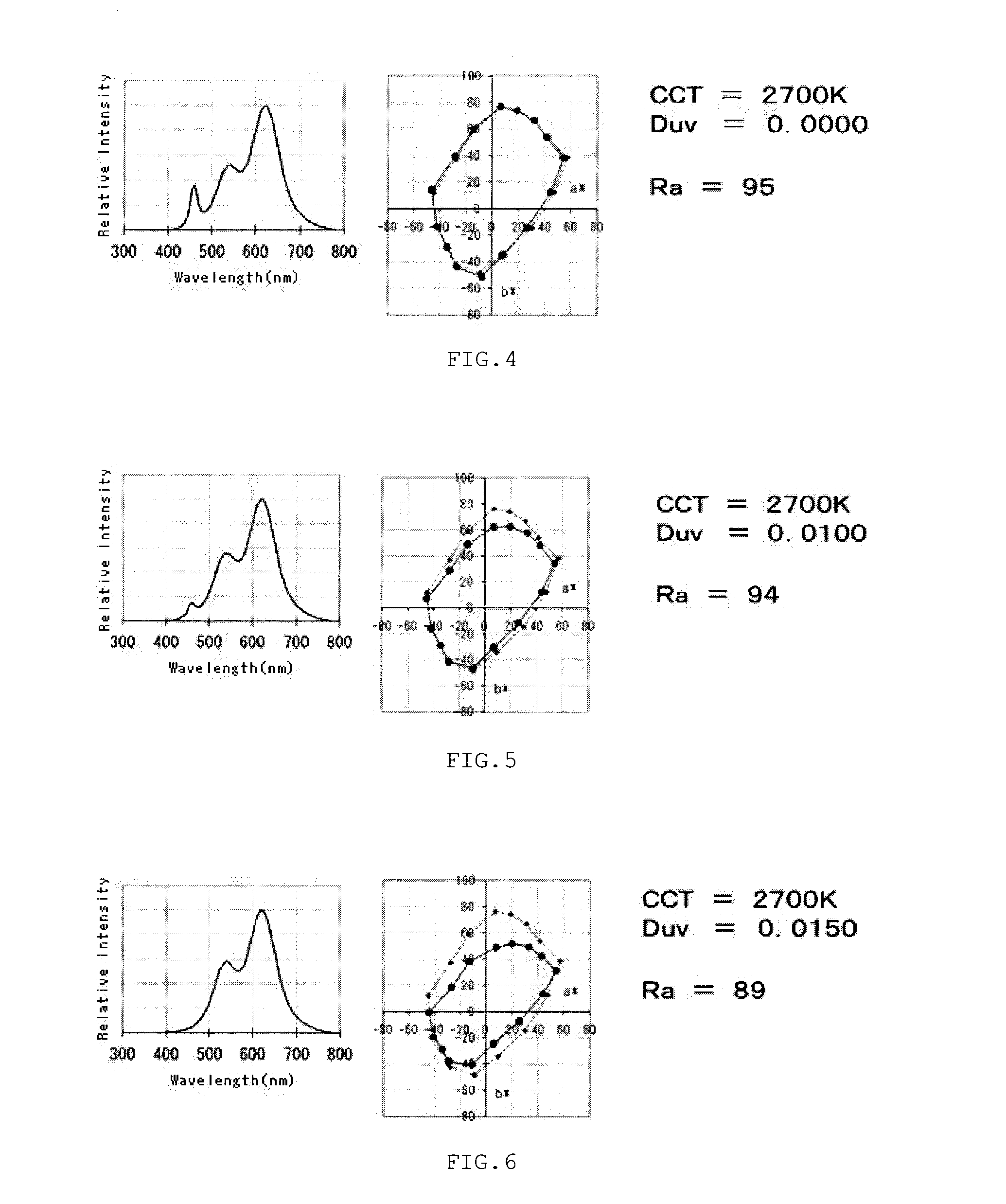
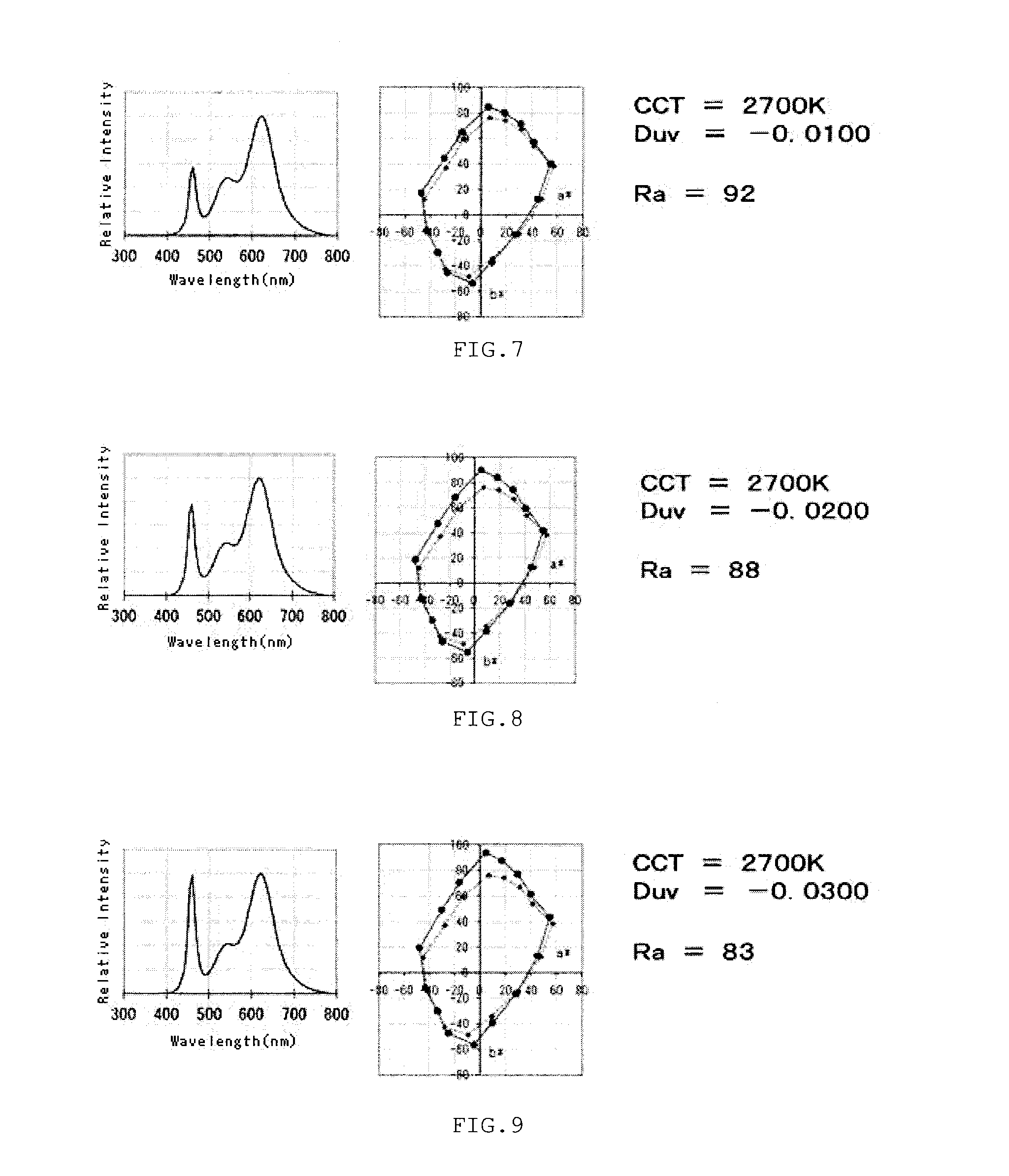
[0251]First, Duv was as considered heretofore and was −0.0075 or lower, more favorably −0.0100 or lower, extremely favorably −0.0120 or lower, and dramatically favorably −0.0160 or lower.

[0252]In addition, Duv according to the present invention was −0.0325 or higher, favorably −0.0290 or higher, more favorably −0.0250 or higher, extremely favorably −0.0230 or higher, and dramatically favorably −0.0200...


PUM


Abstract

To provide an illumination method and a light-emitting device which are capable of achieving, under an indoor illumination environment where illuminance is around 5000 lx or lower when performing detailed work and generally around 1500 lx or lower, a color appearance or an object appearance as perceived by a person, will be as natural, vivid, highly visible, and comfortable as though perceived outdoors in a high-illuminance environment, regardless of scores of various color rendition metric. Light emitted from the light-emitting device illuminates an object such that light measured at a position of the object satisfies specific requirements. A feature of the light-emitting device is that light emitted by the light-emitting device in a main radiant direction satisfies specific requirements.

Description

CROSS-REFERENCE TO RELATED APPLICATION[0001]This is a continuation of International Application PCT / JP2012 / 072143, filed on Aug. 31, 2012, and designated the U.S., (and claims priority from Japanese Patent Application 2011-192141 which was filed on Sep. 2, 2011 and Japanese Patent Application 2011-192143 which was filed on Sep. 2, 2011) the entire contents of which are incorporated herein by reference.TECHNICAL FIELD[0002]The present invention relates to an illumination method by which light emitted from a light-emitting device illuminates an object, and to a light-emitting device in general incorporating a light-emitting element.BACKGROUND ART[0003]Recent advances toward higher output and higher efficiency in GaN related semiconductor light-emitting elements have been dramatic. In addition, active research is underway to increase efficiency of semiconductor light-emitting elements and various phosphors that use an electron beam as an excitation source. As a result, power-saving cap...

Claims


Application Information

Patent Timeline
Patent Type & Authority Applications(United States)
IPC IPC(8): H01L27/15F21K99/00H05B33/02H05B44/00
CPCH01L27/156H05B33/02F21K9/00H01L33/502F21Y2115/10F21K9/233H05B45/22H05B45/20H01L33/50H01L33/06H01L33/28H01L33/32H01L33/504
Inventor HORIE, HIDEYOSHI
Owner CITIZEN ELECTRONICS CO LTD
Why Eureka
Try Eureka