Tester for lightning arresters counter

Inactive Publication Date: 2014-07-03
YAZDINIA SEYED HASAN
View PDF3 Cites 2 Cited by
  • Summary
  • Abstract
  • Description
  • Claims
  • Application Information

AI Technical Summary

Benefits of technology

[0004]This invention is related to testing of various kinds of discharge counters to find out the accuracy of discharge counter function.

Problems solved by technology

Considering that there was no device for testing the accuracy of discharge counter function, there was no insurance that the counter worked well or not.
Therefore the accuracy of the lightning arrester function wasn't spe

Method used


Image

  • Tester for lightning arresters counter
  • Tester for lightning arresters counter

Examples


Example

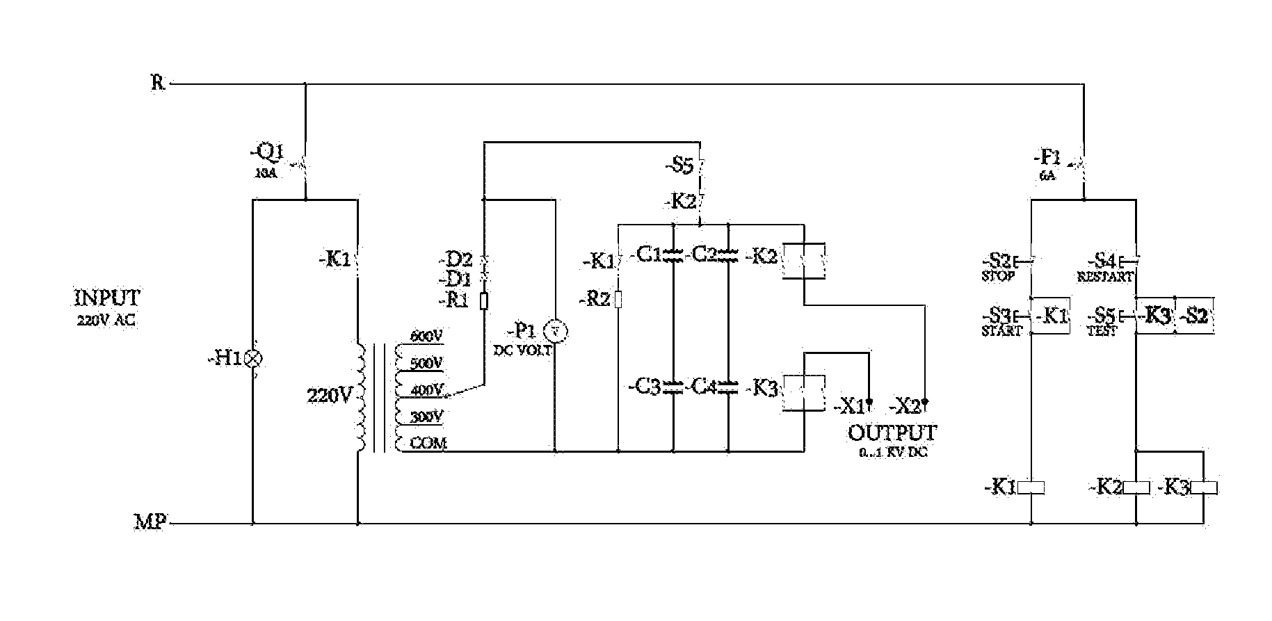
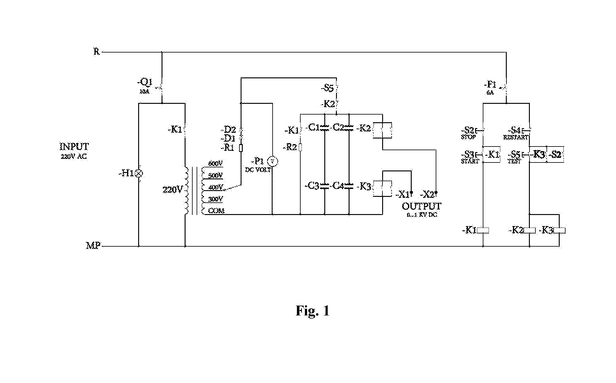
[0006]When fuse Q1 is connected to an input voltage 220 VAC, it supplies the power circuit and an H1 lamp which turns on, this shows the fuse works well and the input voltage is connected. By pushing a start button, contactor K1 is energized and the input voltage supplies primary transformer. The power supply transformer is an increasing transformer (220V / 300-400-500-600-700 V). Depending on the state of voltage charge selector, the chosen voltage after passing resistance R1 (10 W / 47 KΩ and diodes D1, D2 (1KV / 3A) gets rectified in a half wave form and capacitor C1,C2,C3,C4 start to charge.

[0007]Capacitor C1, C2, C3, C4 are the same (AC 50 HZ 400V 25KVAR C=3×166 μF). The value of the capacitors charge voltage is shown by dc voltmeter P1.

[0008]When the voltage of capacitors reaches a considered value, with pushing the test button (S5) contactors K2 and K3 are energized and the capacitors' charged voltage will be discharged to the output terminals X1, X2 as an impulse wave. Terminal X2...


PUM


Abstract

The designed circuit is used for testing all kinds of discharge counter for lightning arresters. Discharge counter for lightning arresters are used in substation and all power plants with various voltages and discharge currents. The lightning arresters counter tester creates the needed voltage and current that operates the counter and simulates the conditions that the counter works in; therefore it can be concluded whether the counter works well or not.

Description

BACKGROUND OF THE INVENTION[0001]U.S. Pat. No. 3,469,188 A (Hall) describes a circuit for use with lightning arresters to provide a measure of the grading current and leakage current associated with the arresters as well as to count the number of surges occurring through the arresters and also in U.S. Pat. No. 4,338,648 (Subbarao) describes gapless discharge counter for lightning arresters.[0002]The discharge counter is connected between the surge arrester and ground, monitors the steady state current by means of an ammeter and records the number of discharges by means of a capacitor, cyclometer coil, and a recorder. Regarding These parameters the accuracy or having malfunction in lightning arresters can be determined[0003]The lightning arresters are used in substations to protect the equipment against the excessive voltage that are produced because of surge or switching. Considering that there was no device for testing the accuracy of discharge counter function, there was no insura...

Claims


Application Information

Patent Timeline
IPC IPC(8): G01R31/327
CPCG01R31/3278G01R31/2839G01R31/2827G01R31/3277H02H3/044
Inventor YAZDINIA, SEYED HASAN
Owner YAZDINIA SEYED HASAN
Why Eureka
Try Eureka