
Efficient intercept of connection-based transport layer connections

a technology of transport layer connection and efficient intercept, which is applied in the direction of digital transmission, data switching network, instruments, etc., can solve the problem that the operation of the tcp control loop between the client and the proxy may be unduly disturbed

Active Publication Date: 2014-07-03
NETRONOME SYST
View PDF8 Cites 62 Cited by
  • Summary
  • Abstract
  • Description
  • Claims
  • Application Information

AI Technical Summary

Benefits of technology

The patent describes a technology that allows a device to analyze and modify packets of a TCP connection. By using two TCP control loops, the device can hold packets for analysis and modification without disrupting the overall connection. The technical effect is improved performance and efficiency in analyzing and managing TCP connections.

Problems solved by technology

If TCP / IP packets are delayed and not ACKed back to the client device, then operation of the TCP control loop between the client and proxy may be unduly disturbed.

Method used


Image

  • Efficient intercept of connection-based transport layer connections
  • Efficient intercept of connection-based transport layer connections
  • Efficient intercept of connection-based transport layer connections

Examples


Embodiment Construction

[0036]Reference will now be made in detail to some embodiments of the invention, examples of which are illustrated in the accompanying drawings.

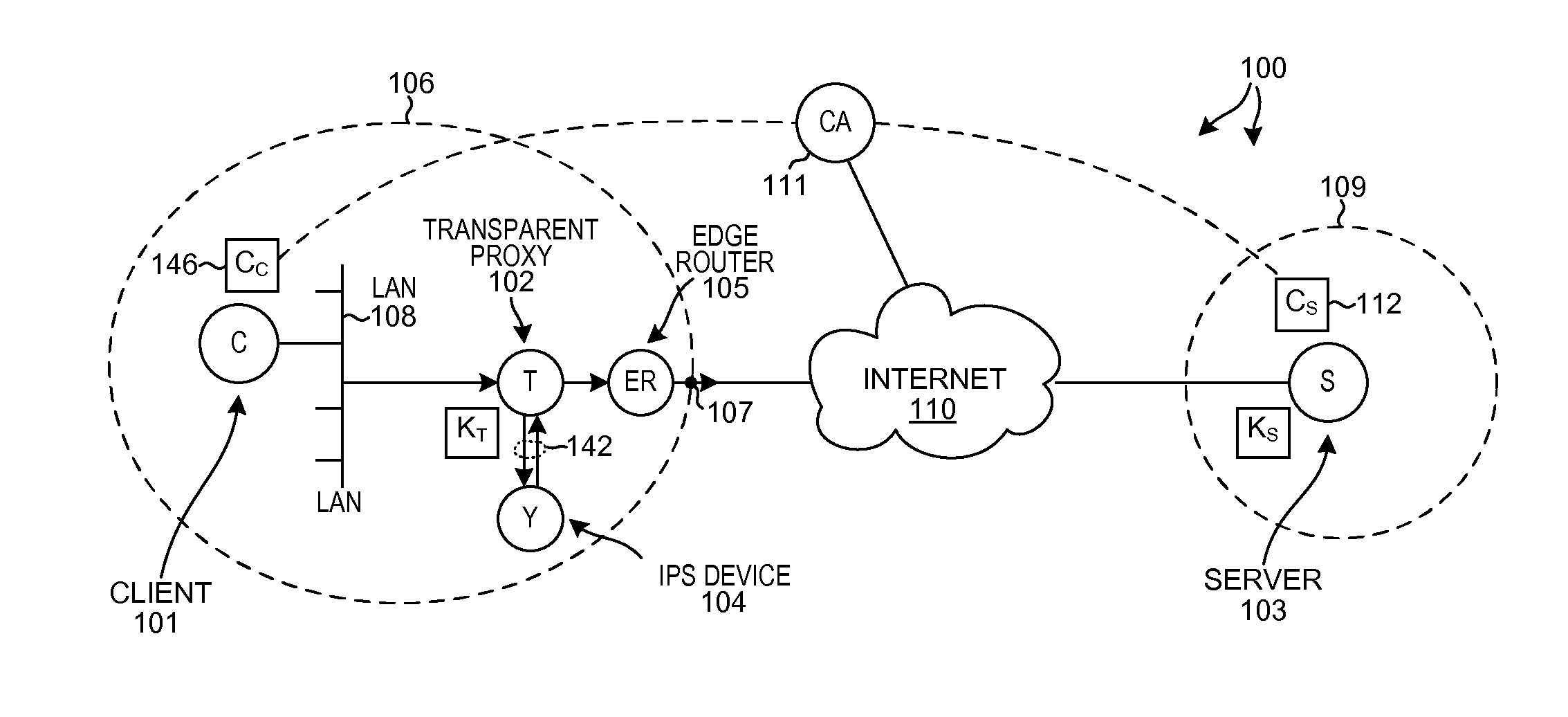
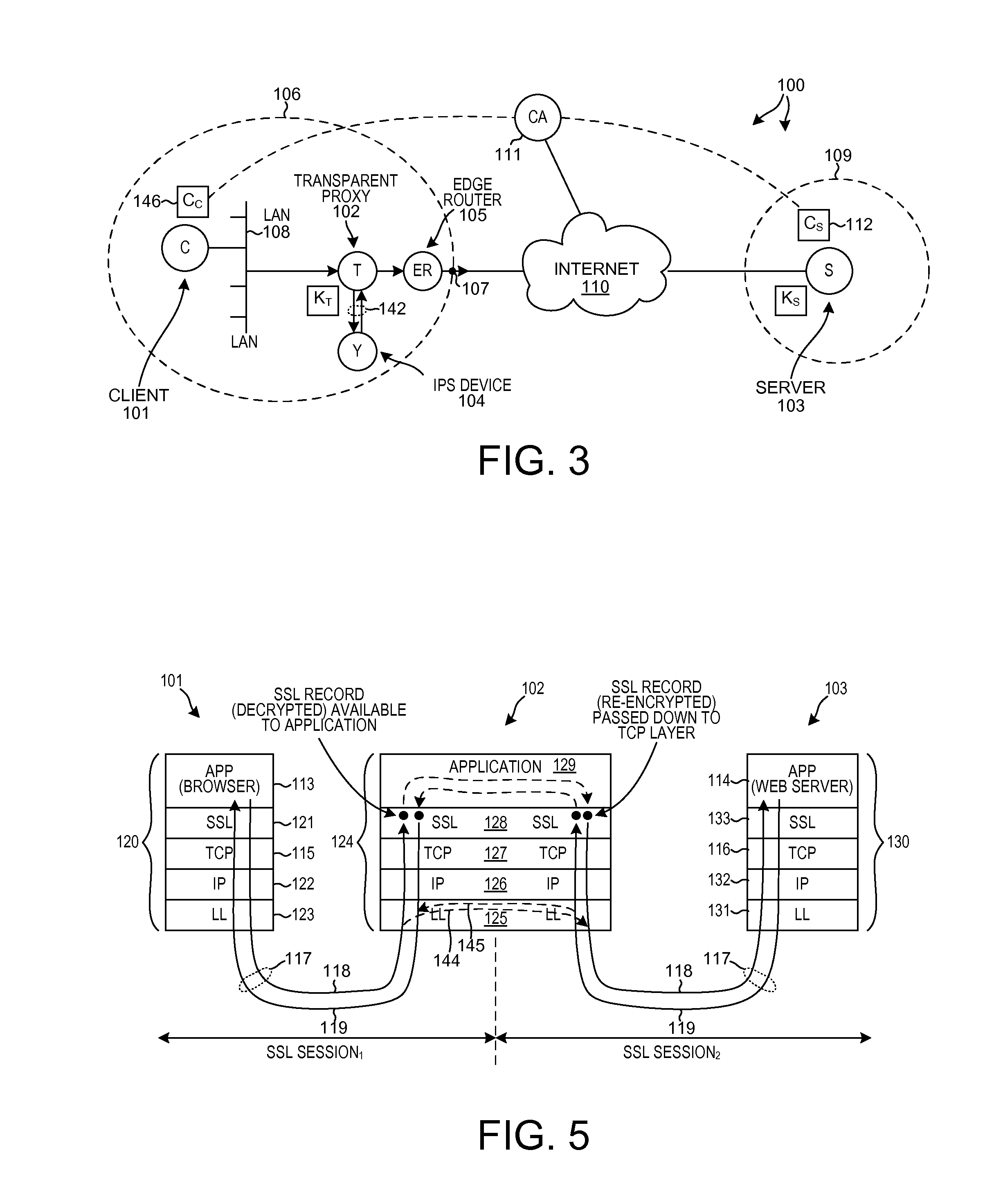
[0037]FIG. 3 is a diagram of a system 100 that includes a novel transparent proxy device in accordance with one novel aspect. System 100 includes a first network device 101, a second device network device 102, a third network device 103, a fourth network device 104, and a fifth network device 105. In this example, first network device 101 is a client device, second network device 102 is the novel transparent proxy device, third network device 103 is a server device, fourth network device 104 is an IPS (Intrusion Prevention System) and recording device, and fifth network device 105 is an edge router. Dashed line 106 represents the boundary of a first company or organization. Dot 107 identifies an edge of the network of the first organization through which communications between the company 106 and the internet 110 pass. Client device 101 can ...


PUM


Abstract

A TCP connection is established between a client and a server, such that packets communicated across the TCP connection pass through a proxy. Based at least in part on a result of monitoring packets flowing across the TCP connection, the proxy determines whether to split the TCP control loop into two TCP control loops so that packets can be inspected more thoroughly. If the TCP control loop is split, then a first TCP control loop manages flow between the client the proxy and a second TCP control loop manages flow between the proxy and the server. Due to the two control loops, packets can be held on the proxy long enough to be analyzed. In some circumstances, a decision is then made to stop inspecting. The two TCP control loops are merged into a single TCP control loop, and thereafter the proxy passes packets of the TCP connection through unmodified.

Description

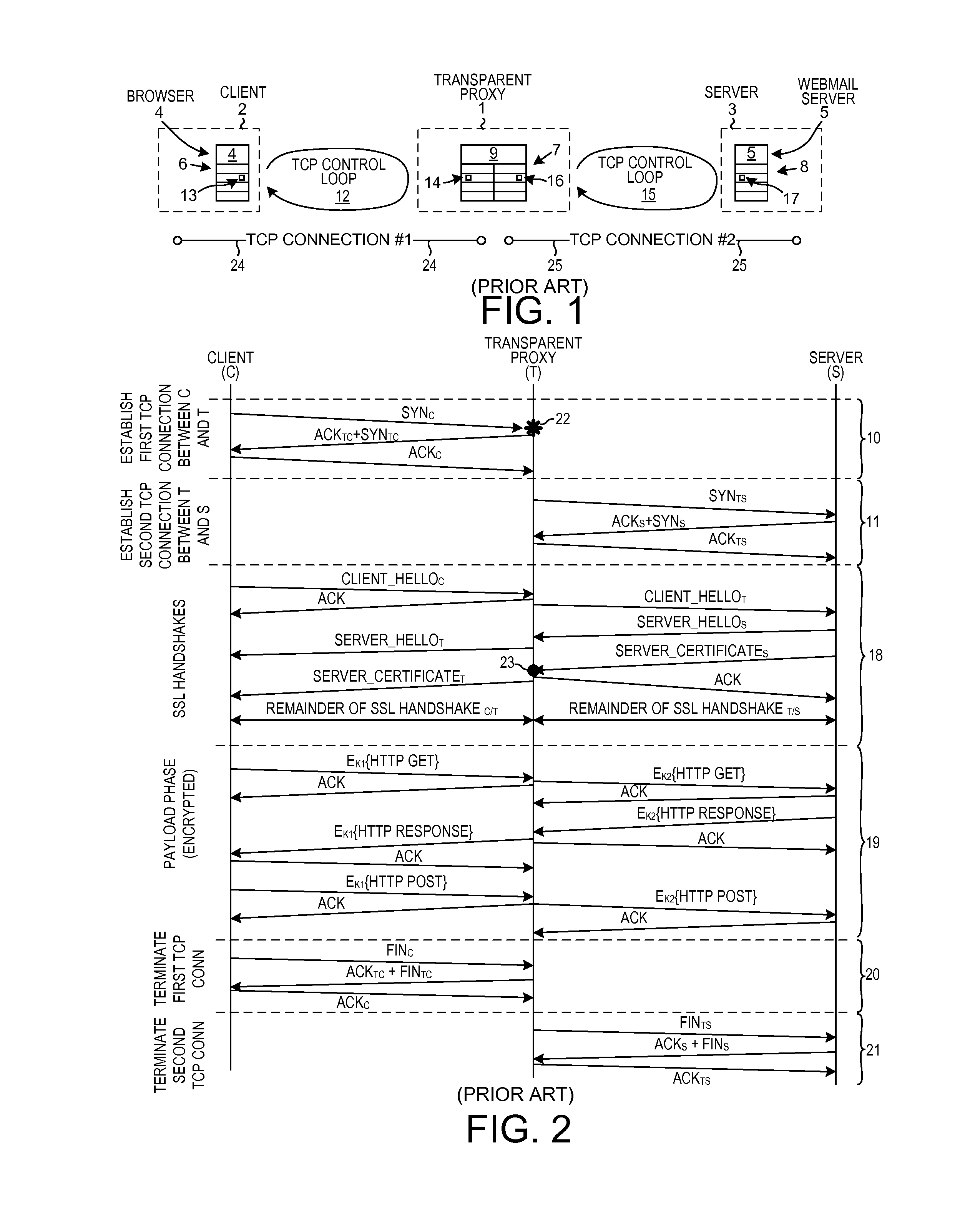
TECHNICAL FIELD[0001]The described embodiments relate generally to transparent proxy devices.BACKGROUND INFORMATION[0002]FIG. 1 (Prior Art) is a diagram that illustrates an operation of a network device loosely referred to as a transparent proxy 1. There are many variants of transparent proxy devices. The transparent proxy 1 illustrated in FIG. 1 is but one example. In one operational example, a client device 2 is part of a company network. An application layer program 4 running on the client device 2 wishes transmit information out of the company network and across the internet to an application program 5 running on a server device 3. The application layer program 4 running on the client device 2 in this example is a web browser. The application layer program 5 running on the server device 3 in this example is a web server that serves email (i.e., a webmail server). The information to be exchanged is an email that browser 4 sends to web server 5 over an encrypted link.[0003]A proto...

Claims


Application Information

Patent Timeline
Patent Type & Authority Applications(United States)
IPC IPC(8): H04L12/56H04L29/06
CPCH04L29/06H04L47/10H04L69/163H04L63/0281H04L63/0464H04L63/0823H04L63/166H04L9/40
Inventor DU TOIT, ROELOF NICOFOURIE, JACQUESDJALALIEV, PETER LIUDMILOV
Owner NETRONOME SYST
Learn More