
Electronic apparatus, and method of controlling an electronic apparatus through motion input

a technology of electronic equipment and remote controller, which is applied in the field of electronic equipment, can solve the problems of limiting the effective use of various functions of electronic equipment, affecting the user's experience, and causing users to be inconvenienced

Inactive Publication Date: 2014-07-03
SAMSUNG ELECTRONICS CO LTD
View PDF12 Cites 6 Cited by
  • Summary
  • Abstract
  • Description
  • Claims
  • Application Information

AI Technical Summary

Benefits of technology

The patent is about a device that can change the distance between two pointers using motion input. The device can also enhance or reduce the image display on the screen based on the user's command. This technology allows for intuitive interaction with the device using hand gestures, making it more user-friendly and efficient.

Problems solved by technology

However, those simple input methods put a limit on effective use of various functions of electronic apparatuses.
In such a situation, it is not easy for users to become accustomed to a method of using such a remote controller.
In addition, if all menus are displayed on the screen, users are required to go through complicated menu trees one by one in order to select a desired menu, which causes great inconvenience to the users.
However, related-art motion recognition technology uses a single object or body and thus puts a limit on using modern electronic apparatuses that require various input methods.
However, it is understood that one or more exemplary embodiment are not required to overcome the disadvantages described above, and may not overcome any of the problems described above.

Method used


Image

  • Electronic apparatus, and method of controlling an electronic apparatus through motion input
  • Electronic apparatus, and method of controlling an electronic apparatus through motion input
  • Electronic apparatus, and method of controlling an electronic apparatus through motion input

Examples


Embodiment Construction

[0039]Hereinafter, exemplary embodiments will be described in greater detail with reference to the accompanying drawings.

[0040]In the following description, the same reference numerals are used for the same elements when they are depicted in different drawings. The matters defined in the description, such as detailed construction and elements, are provided to assist in a comprehensive understanding of the exemplary embodiments. Thus, it is apparent that exemplary embodiments can be carried out without those specifically defined matters. Also, functions or elements known in the related art are not described in detail since they would obscure the exemplary embodiments with unnecessary detail.

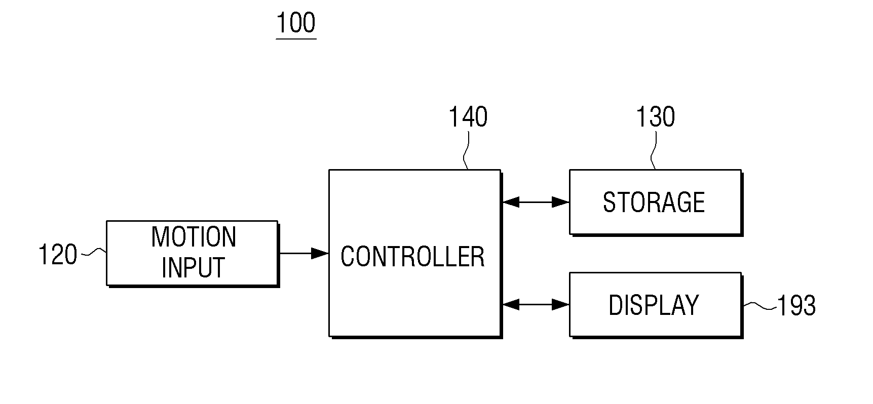
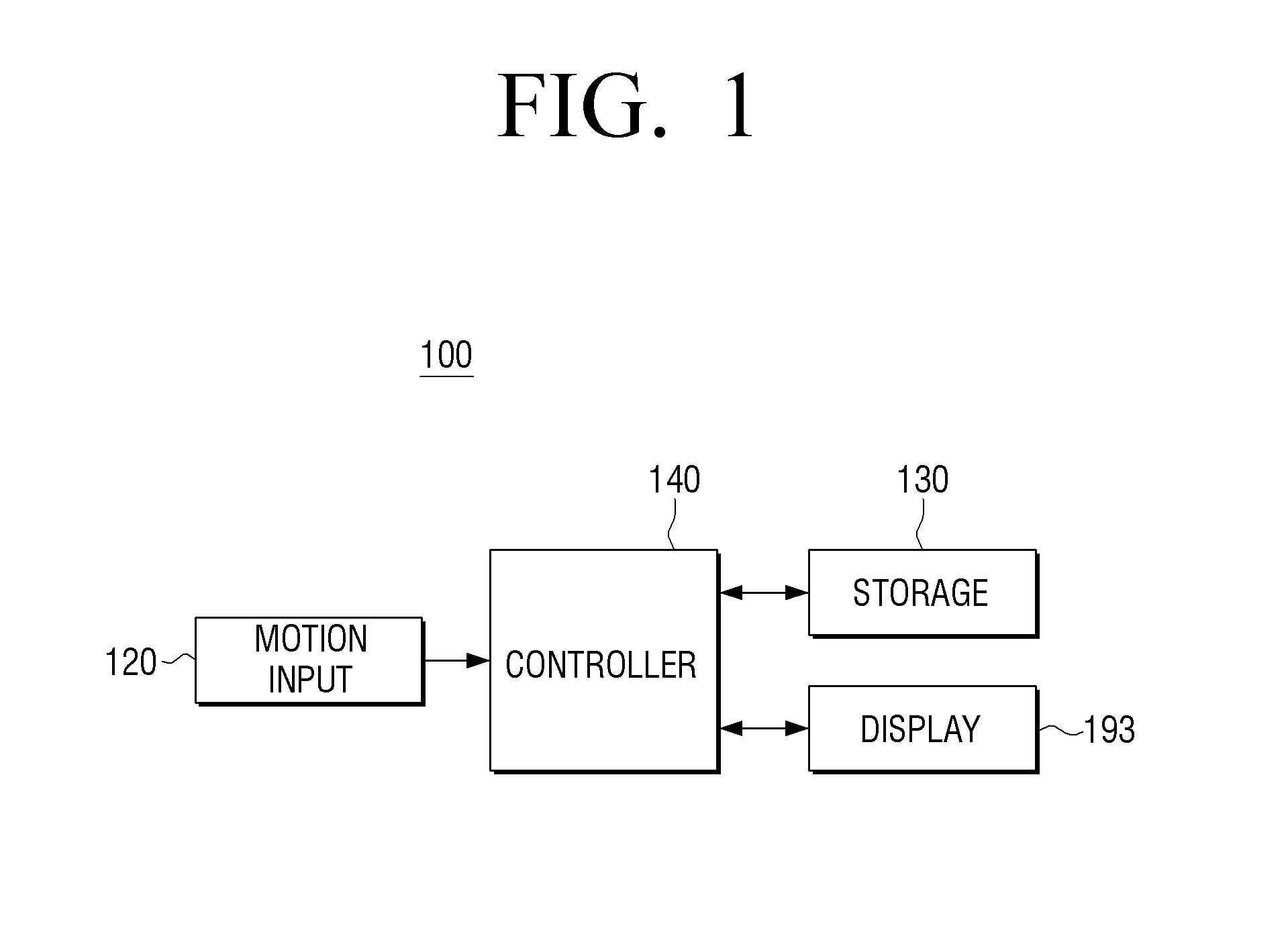
[0041]FIG. 1 is a block diagram which schematically illustrates an electronic apparatus 100 according to an exemplary embodiment. Referring to FIG. 1, the electronic apparatus 100 includes a motion input 120, a storage 130, a controller 140, and a display 193. The electronic apparatus 100 may be a...


PUM


Abstract

An electronic apparatus and a control method thereof for controlling through motion input are provided. The method for controlling the electronic apparatus includes: in response to a predetermined mode trigger command being input, changing a mode of the electronic apparatus to a first motion task mode in which a motion task is performed using two pointers; in response to the mode being changed to the first motion task mode, displaying a UI to perform the first motion task mode on a display screen; and, in response to a user motion command using the two pointers being input, performing a motion task which corresponds to the user motion command, and displaying information on the performed motion task on the display screen.

Description

CROSS-REFERENCE TO RELATED APPLICATION[0001]This application claims priority from Korean Patent Application No. 10-2012-0155207, filed on Dec. 27, 2012 in the Korean Intellectual Property Office, the disclosure of which is incorporated herein by reference, in its entirety.BACKGROUND[0002]1. Field[0003]Methods and apparatuses consistent with exemplary embodiments relate to an electronic apparatus and a control method thereof. More particularly, the exemplary embodiments relate to an electronic apparatus which is controlled according to a user motion input through a motion input, and a control method thereof.[0004]2. Description of the Related Art[0005]With the development of electronic technologies, various kinds of electronic apparatuses have been developed and distributed. In particular, various types of electronic apparatuses including a television (TV) are being widely used in households. Such electronic apparatuses are equipped with a wide variety of functions in order to live u...

Claims


Application Information

Patent Timeline
Patent Type & Authority Applications(United States)
IPC IPC(8): H04N21/422H04N21/4782H04N21/482
CPCH04N21/42225H04N21/482H04N21/4782G06F3/04845G06F2203/04806G06F3/04883G06F3/048G06F3/03G06F3/14
Inventor JANG, SUNG-HYUNKIM, JUNG-GEUNLEE, DONG-HEONKIM, JAE-KWON
Owner SAMSUNG ELECTRONICS CO LTD
Learn More