Image forming apparatus provided with mechanism for cleaning image carrier

a technology of image carrier and forming apparatus, which is applied in the direction of electrographic process apparatus, instruments, optics, etc., can solve the problems of image blurring, streaks and image blurring, and streaks, so as to reduce image blurring, color misalignment, and streaks. , to achieve the effect of reducing phase difference, reducing streaks and image blurring, and increasing the first print-out tim

Inactive Publication Date: 2011-05-05
CANON KK
View PDF3 Cites 3 Cited by
  • Summary
  • Abstract
  • Description
  • Claims
  • Application Information

AI Technical Summary

Benefits of technology

[0008]In view of this, a feature of the present invention is to solve at least one of such problems and other problems. For example, a feature of the present invention is to reduce streaks, image blurring, and color misalignment by reducing the phase difference due to the variations between loads on drive sources that drive image carriers without increasing a first print-out time. It should be noted that means to solve the other problems shall become apparent through the entire specification.
[0010]According to the present invention, control is performed such that the final amount of rotation when an image carrier is intermittently driven N times reaches a prescribed amount, thus reducing the phase difference due to variations between loads on the drive sources. Accordingly, it is possible to reduce streaks, image blurring, and color misalignment resulting from the phase difference between the image carriers, without increasing the first print-out time.

Problems solved by technology

However, if the image carrier and a cleaning blade are left in contact with each other, finely-powdered toner, an additive agent, and the like aggregate in such a contact area, which causes streaks and image blurring (density fluctuation and the like) to occur.
This is a cause of streaks and image blurring.
However, Japanese Patent Laid-Open No. 2006-330299 does not take into consideration the cleaning sequence after image formation ends as disclosed in Japanese Patent Laid-Open No. 2005-62280.
Specifically, if the cleaning sequence is executed after the phases are aligned, there is a possibility that the phases may shift again.
This also leads to a possibility of increasing the phase difference between the image carriers.

Method used


Image

  • Image forming apparatus provided with mechanism for cleaning image carrier
  • Image forming apparatus provided with mechanism for cleaning image carrier
  • Image forming apparatus provided with mechanism for cleaning image carrier

Examples


embodiment 1

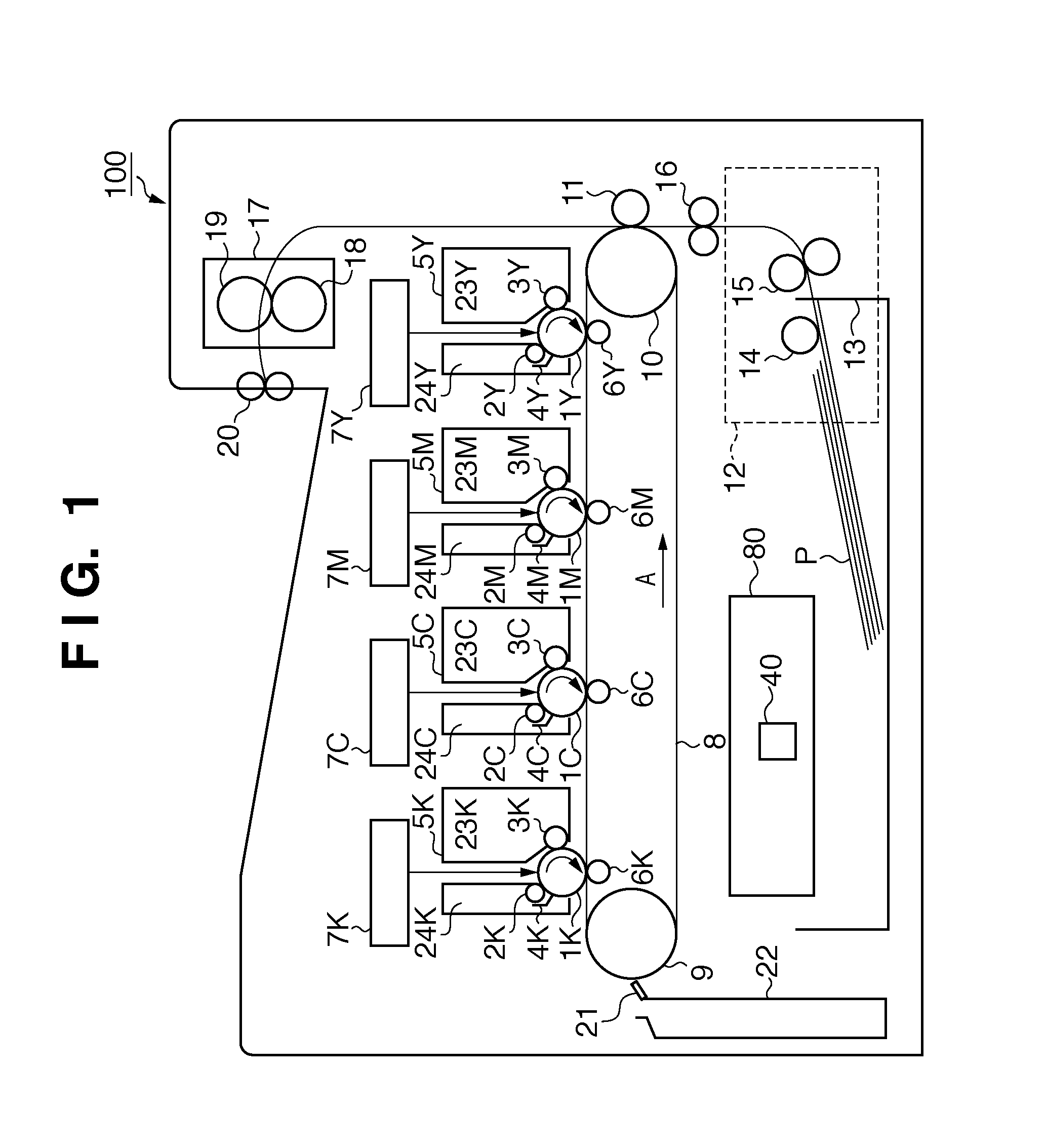
[0030]FIG. 1 is a schematic cross-sectional view of a multicolor image forming apparatus 100 (hereinafter referred to as a main body). YMCK given as the suffix of reference numerals in FIG. 1 denote the colors (yellow, magenta, cyan, and black) of toner, which is a developer. Below, YMCK is omitted when describing aspects in common with all the colors.

[0031]The image forming apparatus 100 is provided with four process cartridges 5 that are detachable from the main body. Although the basic structure of these four process cartridges 5 is the same, the difference thereof is to respectively form images with a different color of toner. Each of the process cartridges 5 has a toner container 23, a photosensitive drum 1 serving as an image carrier, a charging roller 2, a developing roller 3, a drum cleaning blade 4, and a waste toner container 24.

[0032]Laser units 7 are arranged above the process cartridges 5. The laser unit 7 exposes the corresponding photosensitive drum 1 based on an imag...

embodiment 2

[0063]In Embodiment 2, the amounts of rotation for stop instruction issuance Mt that will be applied from the first to (N−1)th intermittent drives are not corrected, and the amount of rotation for stop instruction issuance Mt that will be applied to the Nth final intermittent drive is corrected. Here, the amounts of rotation for stop instruction issuance applied from the first to (N−1)th intermittent drive are set to Mt(N−1). Note that the values of all of MT(1), MT(2), . . . , Mt(N−1) are the same. The target total amount of rotation from when the first intermittent drive starts until when the Nth intermittent drive ends is assumed to be Da. The total amount of rotation measured from when the first intermittent drive starts until when the (N−1)th intermittent drive ends is assumed to be Ca. The amount of rotation for stop instruction issuance applied to the Nth intermittent drive is assumed to be Mt(N). In Embodiment 2, the CPU 40 determines the amount of rotation for stop instruct...

embodiment 3

[0074]In Embodiment 3, a method for correcting the amounts of rotation for stop instruction issuance Mt for the first to (N−1)th drives is the same as in Embodiment 1. However, in Embodiment 3, a method for determining the amount of rotation for stop instruction issuance Mt(N) for the Nth drive is different. Specifically, the CPU 40 determines the amount of rotation for stop instruction issuance Mt(i) for the ith drive (i is a natural number of 2 or more and N−1 or less), based on the target amount of rotation D and the amount of inertial rotation Cl(i−1) due to the (i−1)th drive. The CPU 40 determines the target amount of rotation D(N) for the Nth drive based on the target total amount of rotation Da and the total amount of rotation Ca that has been measured from the start of the first intermittent drive until the end of the (N−1)th intermittent drive. Furthermore, the CPU 40 determines the amount of rotation for stop instruction issuance Mt(N) for the Nth drive, which is the drive...


PUM


Abstract

A control unit temporarily stops an image carrier when transfer of an image formed using a developer to a recording medium ends. Thereafter, the control unit controls a drive source to intermittently drive the image carrier N times. A measuring unit measures an amount of rotation of the image carrier when the image carrier is intermittently driven. A determination unit determines an amount of rotation for stop instruction issuance that will be applied to a next drive. The amount of rotation for stop instruction issuance is based on an amount of inertial rotation measured from when a stop instruction is issued until when the image carrier stops rotating, and a target amount of rotation for each time the image carrier is driven.

Description

BACKGROUND OF THE INVENTION[0001]1. Field of the Invention[0002]The present invention generally relates to an image forming apparatus that is provided with image carriers, and in particular to control for cleaning the image carriers.[0003]2. Description of the Related Art[0004]Transfer-system image forming apparatuses that adopt an electrophotographic process, an electrostatic recording process, or the like need to clean a developer that has not transferred to paper and remains on the surface of an image carrier. However, if the image carrier and a cleaning blade are left in contact with each other, finely-powdered toner, an additive agent, and the like aggregate in such a contact area, which causes streaks and image blurring (density fluctuation and the like) to occur. Generally, a friction coefficient μ of the portion of the surface (peripheral surface) of the image carrier on which finely-powdered toner and the like aggregate relatively becomes lower. Thus, the rotational velocit...

Claims


Application Information

Patent Timeline
Patent Type & Authority Applications(United States)
IPC IPC(8): G03G15/00
CPCG03G15/5008
Inventor ITOH, MASATOSHI
Owner CANON KK
Why Eureka
Try Eureka