Asymmetric liquid crystal actuation system and method

Inactive Publication Date: 2002-12-05
REGENMACHER +1
View PDF0 Cites 4 Cited by
  • Summary
  • Abstract
  • Description
  • Claims
  • Application Information

AI Technical Summary

Problems solved by technology

If electrical charge has been built up at a pixel, however, a change in vol

Method used


Image

  • Asymmetric liquid crystal actuation system and method
  • Asymmetric liquid crystal actuation system and method
  • Asymmetric liquid crystal actuation system and method

Examples


Embodiment Construction

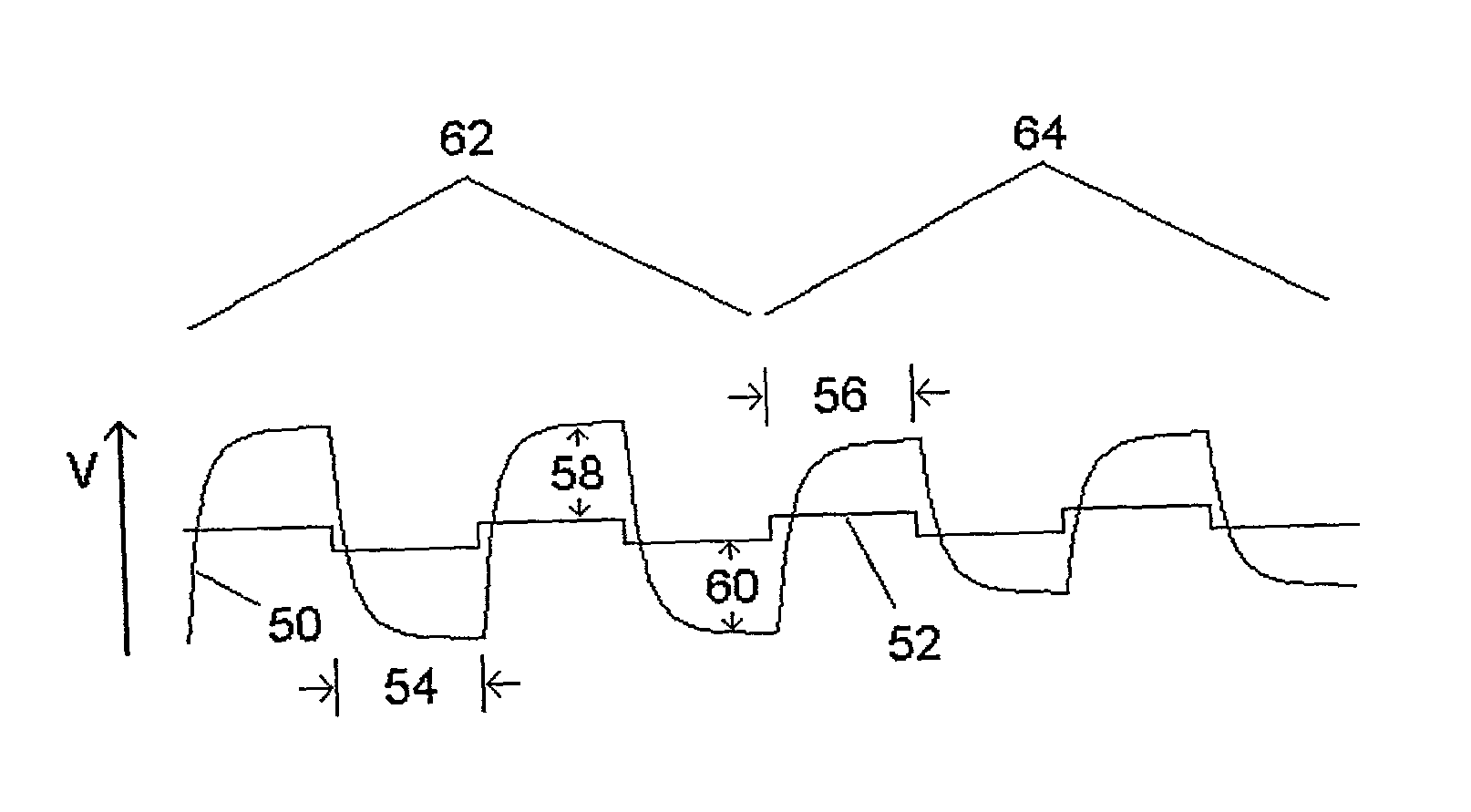
[0022] The present invention is directed to a liquid crystal display (LCD) comprising a matrix of liquid crystal pixels having light modifying properties controlled by voltage values stored in capacitors formed by electrodes located in the matrix of pixels of the LCD. The voltage inputs to the LCD pixels are analog signals with values sequentially above and below a reference or cover voltage of typically from about 7.5 to 8.0 volts. That reference voltage is called "VCOM" and connects to the LCD cover glass electrode which is a transparent conductive coating on the inside face (liquid crystal side) of the cover glass. The transparent conductive coating is typically Indium Tin Oxide (ITO). The video inputs are connected across the liquid crystal cell from the cover glass electrode such that a potential difference is applied across the liquid crystal cell.

[0023] Alternate frames of video pixels are run at voltages above the center reference or cover voltage (positive inversion) and be...


PUM


Abstract

A liquid crystal display (LCD) system, comprising a matrix of pixels, actuates each pixel by applying positive and negative voltage differences across a liquid crystal layer. The liquid crystal layer is parallel to a transparent cover. The transparent cover is adjacent to a cover electrode. Each pixel includes a pixel electrode positioned on the opposite side of the liquid crystal layer from the cover electrode. The positive and negative voltage differences are asymmetric to compensate for polarity-dependent characteristics of the LCD materials. The positive and negative voltage differences are applied for durations that counterbalance the asymmetric rates of charge accumulation.

Description

[0001] The present invention is related to the subject matter disclosed in pending U.S. application Ser. No. 09 / 685,834, which is hereby incorporated by reference in its entirety.[0002] The present invention relates generally to liquid crystal display (LCD) devices, and more particularly to a system and method for asymmetrically actuating a liquid crystal display.BACKGROUND OF THE INVENTION TECHNOLOGY[0003] Liquid crystal displays (LCDs) are commonly used in devices such as portable televisions, portable computers, control displays, and cellular phones to display information to a user. LCDs act in effect as a light valve, i.e., they allow transmission of light in one state, block the transmission of light in a second state, and some include several intermediate stages for partial transmission. When used as a high resolution information display, as in one application of the present invention, LCDs are typically arranged in a matrix configuration with independently controlled display ...

Claims


Application Information

Patent Timeline
IPC IPC(8): G09G3/36
CPCA61M1/0013A61M1/61G09G3/36
Inventor WATERMAN, JOHN KARLWELLMAN, JASON
Owner REGENMACHER
Why Eureka
Try Eureka