Reduction of image jump

Inactive Publication Date: 2011-11-24
PIXELOPTICS
View PDF2 Cites 4 Cited by
  • Summary
  • Abstract
  • Description
  • Claims
  • Application Information

AI Technical Summary

Benefits of technology

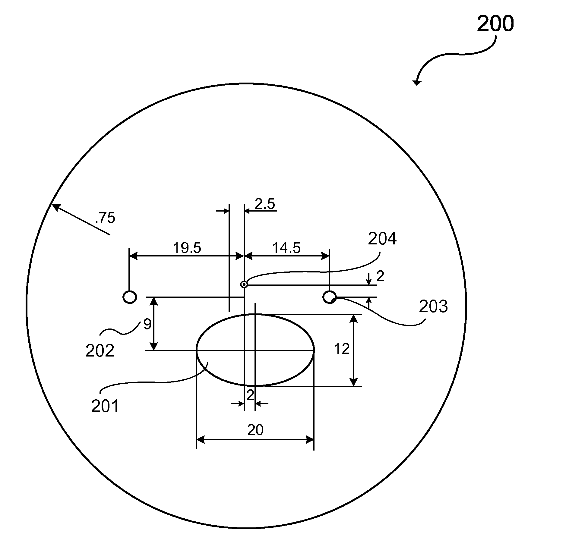
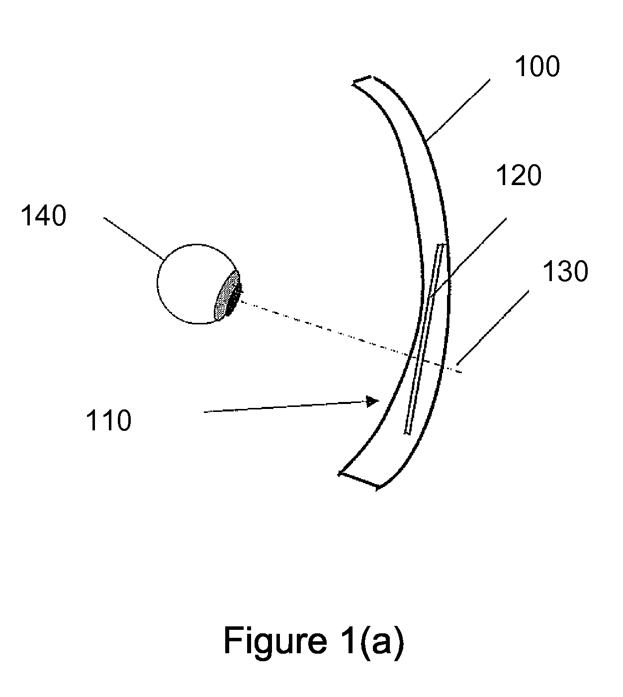
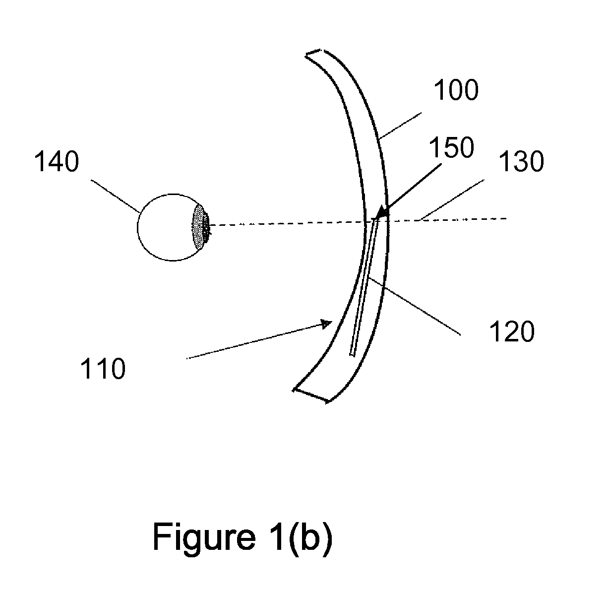
[0030]Embodiments provide apparatuses and systems that may reduce the image jump (both prism displacement and magnification) and/or astigmatism experienced when looking at or across the border between two optical zones that have different optical properties, particularly when one of those zones is dynamic. Embodiments provide a static power optical zone that has a negative optical power in optical communication with at least a portion of the periphery of a dynamic power zone (such as an electro-active segment) that has a positive optical power when activated. In this manner, the total add power of the static power optical zone and the dynamic power zone or region does not ha

Problems solved by technology

This loss of accommodation results in an inability to focus on near distance objects.
While PALs are now widely accepted and in vogue within the USA and throughout the world as a correction for presbyopia, they also have serious vision compromises.
These vision compromises may affect a user's horizontal viewing width, which is the width of the visual field that can be seen clearly as a user looks from side to side while focused at a given distance.
Thus, PAL lenses may have a narrow horizontal viewing width when focusing at an intermediate distance, which can make viewing a large section of a computer screen difficult.
Similarly, PAL lenses may have a narrow horizontal viewing width when focusing at a near distance, which can make viewing the complete page o

Method used


Image

  • Reduction of image jump
  • Reduction of image jump
  • Reduction of image jump

Examples


Example

[0040]Many ophthalmological, optometric, and optical terms are used in this application. For the sake of clarity, their definitions are listed below:

[0041]Add Power: The optical power added to the far distance viewing optical power which is required for clear near distance viewing in a multifocal lens. For example, if an individual has a far distance viewing prescription of −3.00 D with a +2.00 D add power for near distance viewing then the actual optical power in the near distance portion of the multifocal lens is −1.00 D. Add power is sometimes referred to as plus power. Add power may be further distinguished by referring to “near viewing distance add power” which refers to the add power in the near viewing distance portion of the lens and “intermediate viewing distance add power” which refers to the add power in the intermediate viewing distance portion of the lens. Typically, the intermediate viewing distance add power is approximately 50% of the near viewing distance add power....


PUM


Abstract

Embodiments of the present invention disclosed herein are directed to apparatuses and systems for reducing the image jump from a dynamic lens component. The apparatuses and systems disclosed herein may be used in ophthalmic devices, such as eye glasses or contact lenses, as well as any other suitable application. Embodiments provide a first apparatus that comprises a dynamic power zone having a periphery. The first apparatus further comprises a static power zone in optical communication with at least a portion of the dynamic power zone. The static power zone has a negative optical power at a first portion of the periphery of the dynamic power zone.

Description

CROSS-REFERENCES TO RELATED APPLICATIONS[0001]This application claims benefit under 35 U.S.C. §119(e) of U.S. provisional patent application No. 61 / 347,562, filed on May 24, 2010, the entire disclosure of which is incorporated herein by reference for all purposes.BACKGROUND[0002]Presbyopia is the loss of accommodation of the crystalline lens of the human eye that often accompanies aging. This loss of accommodation results in an inability to focus on near distance objects. The standard tools for correcting presbyopia are multifocal ophthalmic lenses. A multifocal lens is a lens that has more than one focal length (i.e., optical power) for correcting focusing problems across a range of distances. Multifocal ophthalmic lenses work by means of a division of the lens's area into regions of different optical powers. Typically, a relatively large area located in the upper portion of the lens corrects for far, distance vision errors, if any. A small area located in the bottom portion of the...

Claims


Application Information

Patent Timeline
IPC IPC(8): G02C7/06G02B3/10
CPCG02C7/083
Inventor GUPTA, AMITAVABLUM, RONALD D.
Owner PIXELOPTICS
Why Eureka
Try Eureka