Reflective optical configurations with prescribed optical field mappings for back-scanned imagers

Active Publication Date: 2019-04-18
RAYTHEON CO
View PDF0 Cites 1 Cited by
  • Summary
  • Abstract
  • Description
  • Claims
  • Application Information

AI Technical Summary

Benefits of technology

[0004]Although back-scanning can hold one field point, e.g., target point 235, relatively stable on the focal plane array (FPA), all other field points may wander during the exposure due to imaging distortion characteristics of the afocal telescope. Aspects and embodiments are directed to optimal field mappings, which can be implemented in reflective optical configurations with controlled distortion characteristics, for back-scanned and line-scanned imagers that reduce field

Problems solved by technology

In certain imaging applications, such as infrared search sensors, for example, it is desirable for the

Method used


Image

  • Reflective optical configurations with prescribed optical field mappings for back-scanned imagers
  • Reflective optical configurations with prescribed optical field mappings for back-scanned imagers
  • Reflective optical configurations with prescribed optical field mappings for back-scanned imagers

Examples


Example

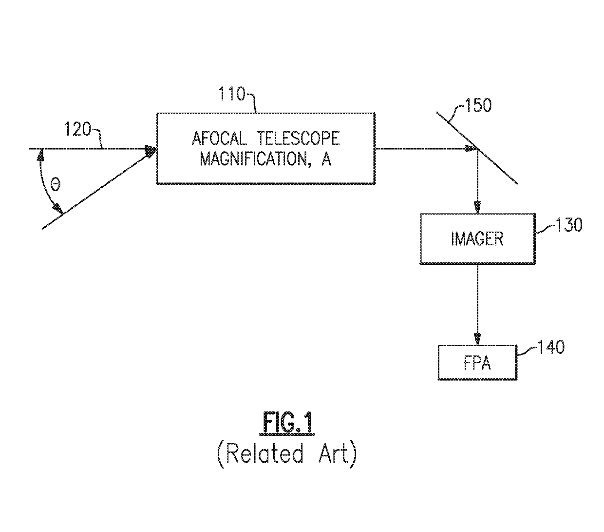
[0028]As discussed above, back-scanned imagers or line-scanned imagers with large fields of view can be used to achieve scanning of the sensor field of view over a large field of regard at a high rate and with diffraction limited performance. However, standard optical design forms introduce image blurring for off-axis field points during the exposure / integration time, which lowers the signal to noise ratio of the target signal.

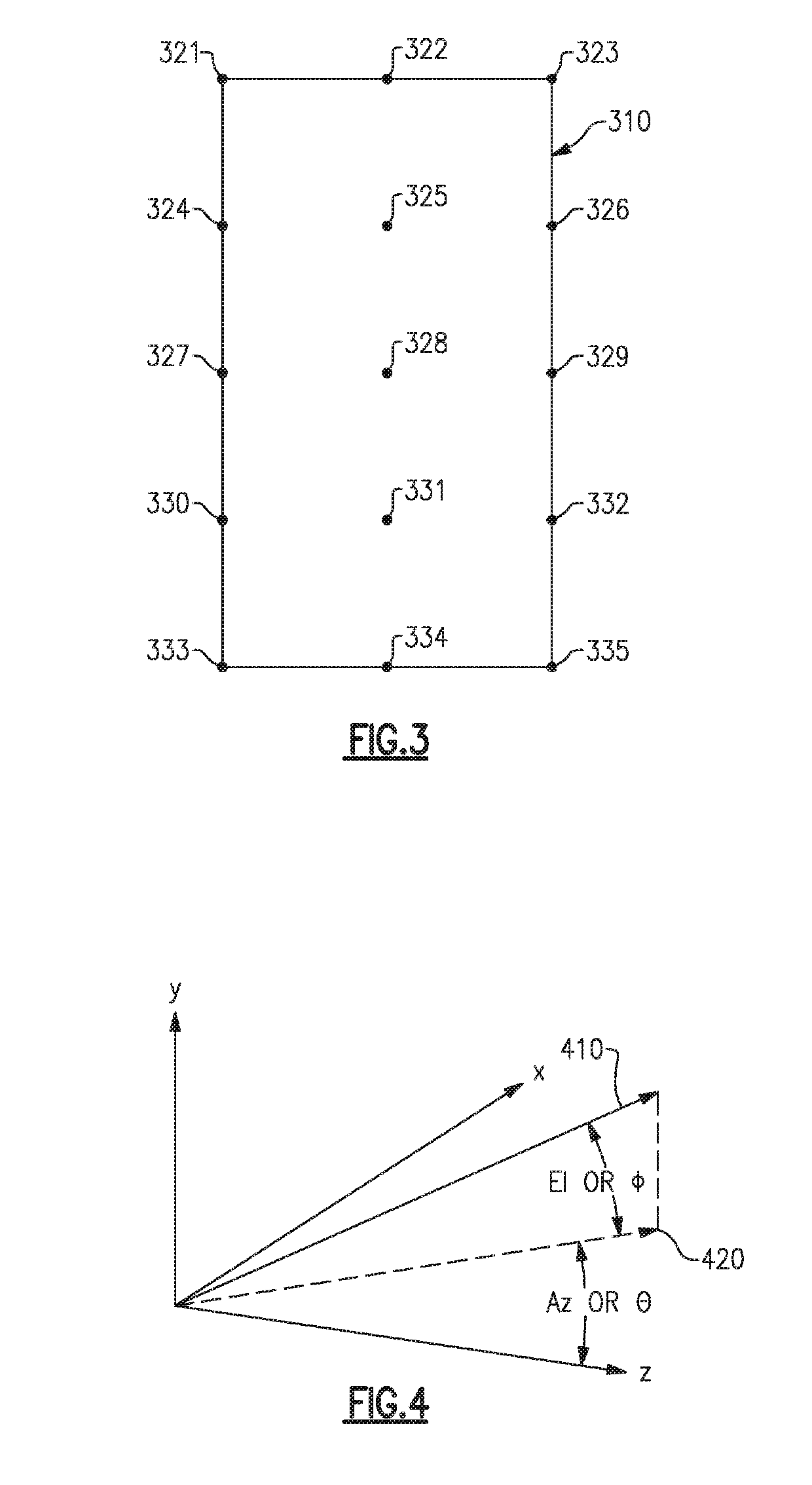
[0029]To further demonstrate the issue of image wander, the following examples consider the case of an infrared search sensor. FIG. 3 schematically illustrates an example of a nominal sensor frame field-of-view (FOV) 310 of an exemplary sensor in object space, showing the locations of a plurality of field points 321-335. The field points include top left 321, top 322, top right 323, left top middle 324, top middle 325, right top middle 326, left 327, on-axis (center) 328, right 329, left bottom middle 330, bottom middle 331, right bottom middle 332, bottom lef...


PUM


Abstract

Optimal angular field mappings that provide the highest contrast images for back-scanned imaging are given. The mapping can be implemented for back-scanned imaging with afocal optics including an anamorphic field correcting assembly configured to implement a non-rotationally symmetric field mapping between object space and image space to adjust distortion characteristics of the afocal optics to control image wander on a focal plane array. The anamorphic field correcting assembly can include one or more mirrors having non-rotationally symmetric aspherical departures.

Description

BACKGROUND[0001]In certain imaging applications, such as infrared search sensors, for example, it is desirable for the imaging sensor to scan large fields of regard at a high rate and with diffraction limited performance. Approaches to achieving these goals include using back-scanned sensors, or line-scan imagers with large fields of view. In order to increase the integration time for a scanned two-dimensional (2-D) imaging sensor, the technique of back-scanning is often used to provide step / stare coverage. FIG. 1 illustrates this concept.[0002]Referring to FIG. 1 there is illustrated a block diagram of one example of a sensor system in which an afocal telescope 110 is configured to receive incoming electromagnetic radiation 120 and direct the radiation via imaging optics 130 to an imaging sensor 140, which is frequently a focal plane array (FPA). Back-scanning with a mirror 150 behind the afocal telescope 110 provides an agile method to increase the integration time for the FPA 140...

Claims


Application Information

Patent Timeline
IPC IPC(8): G02B23/06G02B17/06G02B27/09G02B5/10G02B27/64G02B26/10
CPCG02B13/146G02B17/0663G02B23/02G02B5/10G02B23/06G02B26/10G02B27/0911G02B27/646
Inventor SITTER, JR., DAVID N.
Owner RAYTHEON CO
Why Eureka
Try Eureka