Electromagnetic axle disconnect system

a technology of electronic transmission and axle, applied in the direction of mechanical actuated clutches, interlocking clutches, manufacturing tools, etc., can solve the problems of inability to meet the new requirements of noise, vibration, harshness, etc., and the conventional connection, locking, and disconnecting axle systems are not capable of meeting the new requirements

Active Publication Date: 2014-07-10
DANA AUTOMOTIVE SYST GRP LLC
View PDF3 Cites 28 Cited by
  • Summary
  • Abstract
  • Description
  • Claims
  • Application Information

AI Technical Summary

Benefits of technology

[0008]When the coil is energized, the armature with coil slidably moves the pressure plate and sliding dog clutch into engagement with the axially fixed dog clutch, thereby allowing rotational torque from the input shaft to be transfe

Problems solved by technology

In addition, noise, vibration, and harshness requirements are becoming more stringent, while response time of no more than 200 milliseconds from a time of receiving a command signal is required.
Unfortunately, conventional connecting, locking, and disconnecting axles systems, which are based

Method used


Image

  • Electromagnetic axle disconnect system
  • Electromagnetic axle disconnect system
  • Electromagnetic axle disconnect system

Examples


Embodiment Construction

[0020]It is to be understood that the invention may assume various alternative orientations and step sequences, except where expressly specified to the contrary. It is also to be understood that the specific devices and processes illustrated in the attached drawings, and described in the following specification are simply exemplary embodiments of the inventive concepts defined in the appended claims. Hence, specific dimensions, directions or other physical characteristics relating to the embodiments disclosed are not to be considered as limiting, unless the claims expressly state otherwise.

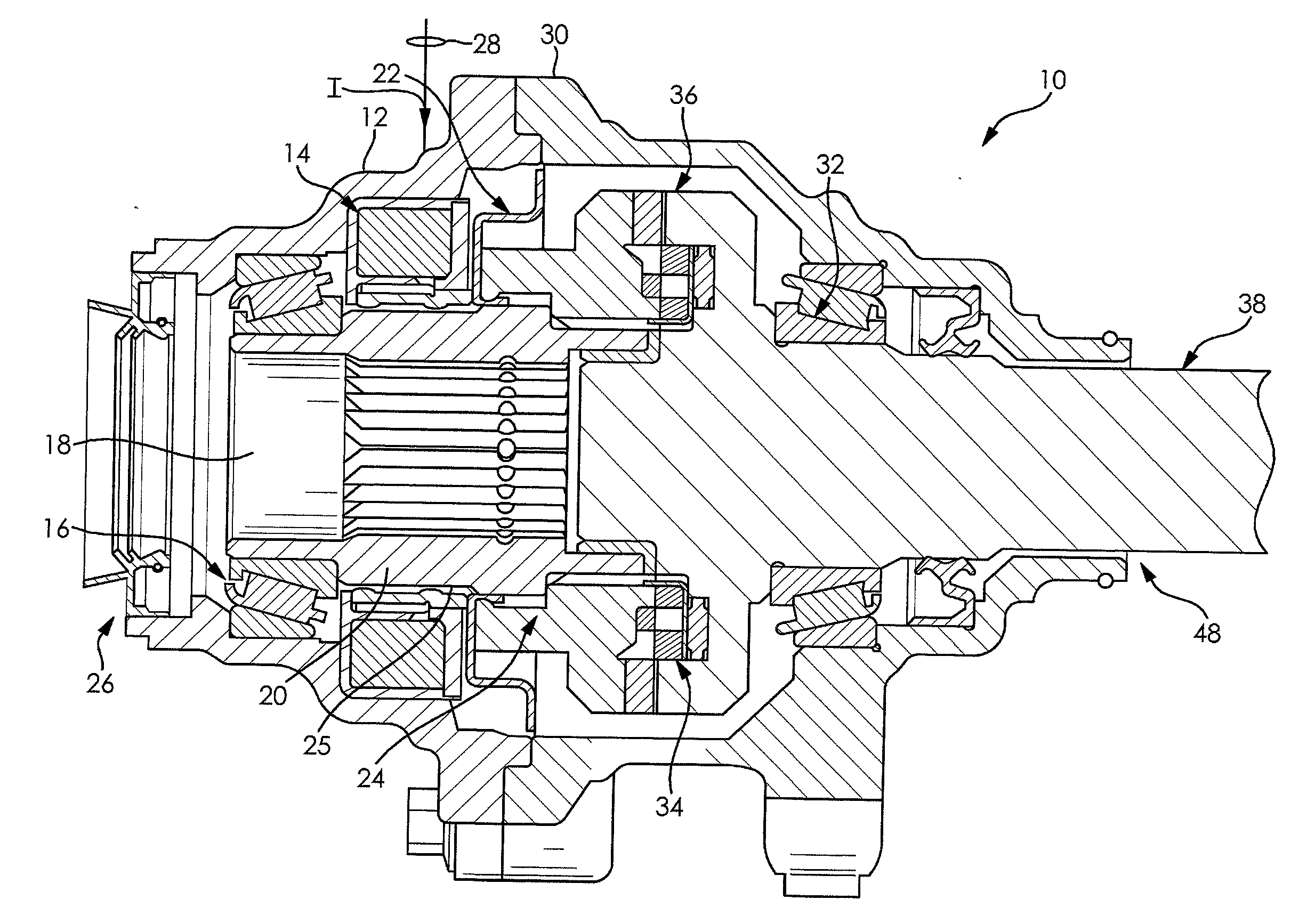
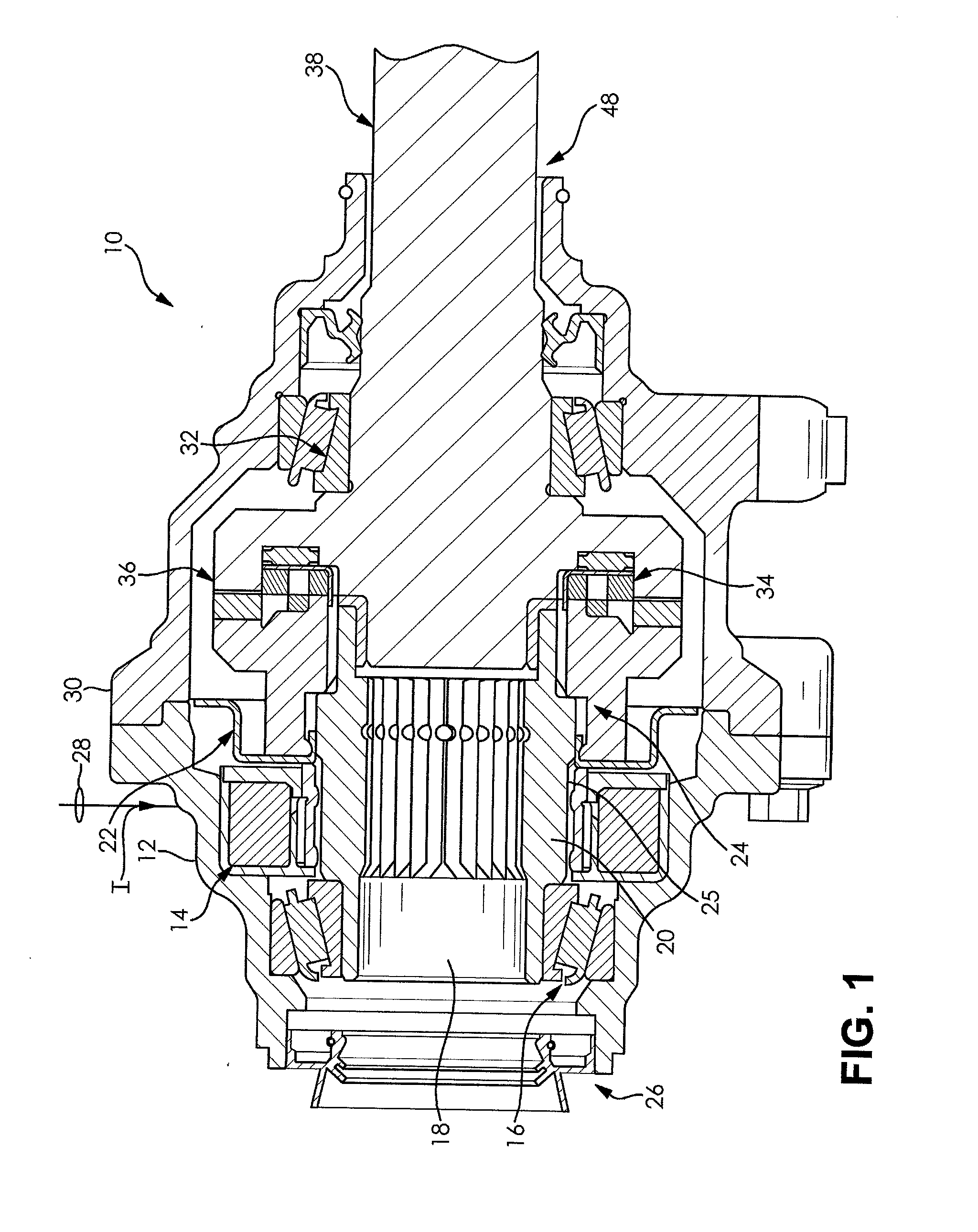
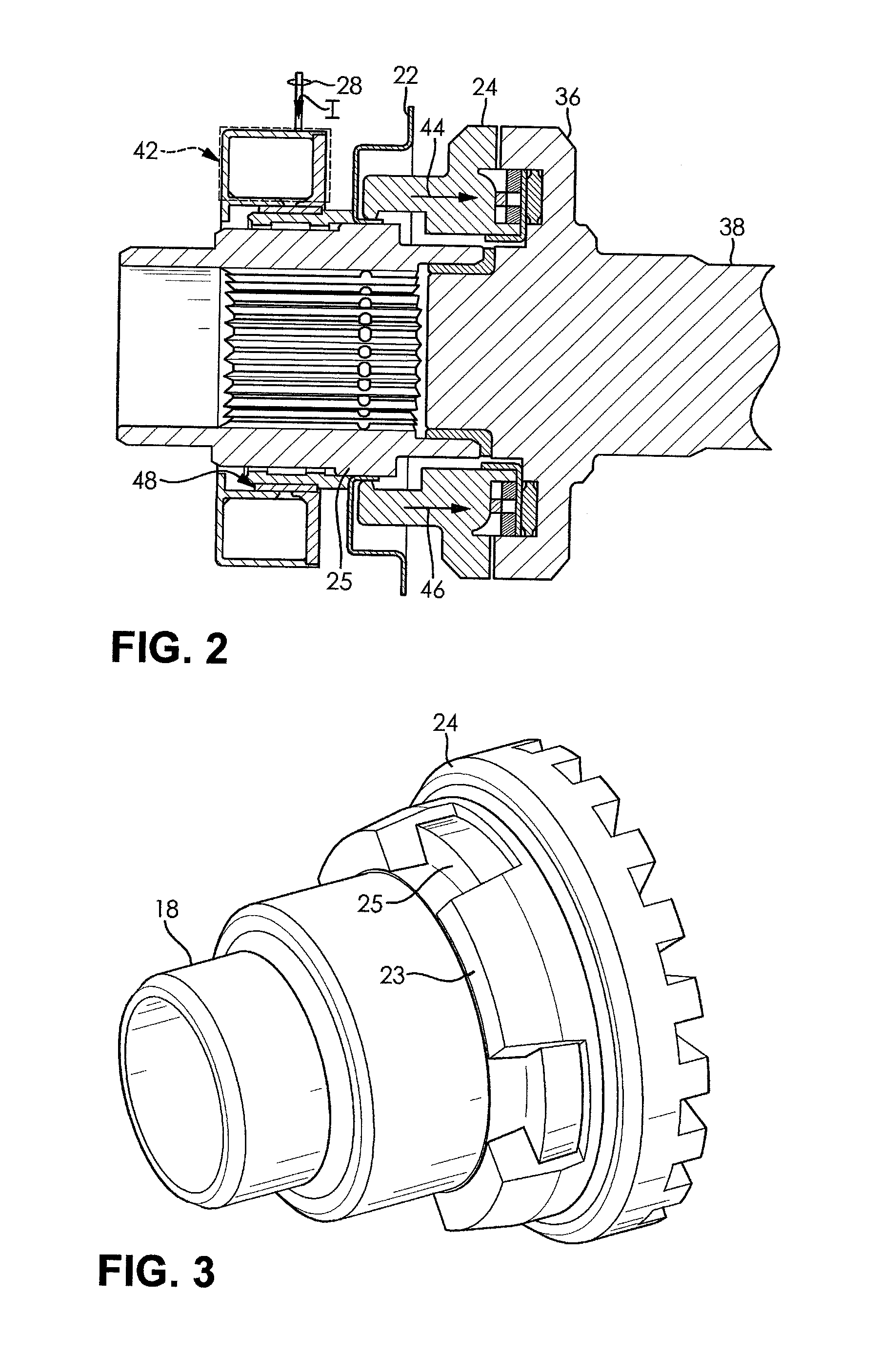
[0021]FIG. 1 illustrates an electromagnetic disconnect system 10 in a mechanically disengaged position that comprises an output housing 12 having an armature with a coil 14 and an output shaft bearing 16 fixedly attached thereto. An output shaft 18 has splines 20 disposed on end thereof, where a pressure plate 22 and a sliding dog clutch 24 are slidably attach to output shaft cams 25 of the output...


PUM

PropertyMeasurementUnit
Timeaaaaaaaaaa
Forceaaaaaaaaaa
Torqueaaaaaaaaaa

Abstract

An electromagnetic disconnect system has an output housing having an armature with a coil and an output shaft bearing fixed to it. A pressure plate and a sliding dog clutch are slidably attached to an output shaft that is in rotational contact with the output shaft bearing. This system further has an input housing attached to the output housing. The input housing has an input shaft bearing fixed to it. The electromagnetic disconnect system further has a disengagement spring and an axially fixed dog clutch rigidly attached to an end of an input shaft that is axially dispose through an opening in the input housing and in rotational contact with the input shaft bearing.

Description

RELATED APPLICATION[0001]This application claims the benefit under 35 U.S.C. §119(e) of U.S. Provisional Patent Application Ser. No. 61 / 750,597, filed Jan. 9, 2013 and U.S. Provisional Patent Application Ser. No. 61 / 750,683, filed Jan. 9, 2013, and which are incorporated by reference herein in their entirety.FIELD OF THE INVENTION[0002]The present invention relates to connecting, locking, and disconnecting axles within a vehicle. More particularly, the present invention relates to electromagnetically connecting, mechanically securing, and disconnecting axles within a vehicle.BACKGROUND OF THE INVENTION[0003]In order to switch a vehicle between two-wheel and all-wheel drive, typically, an electromechanical actuator means is used (see, for example, U.S. Pat. No. 5,788,008 to Fort). In order to secure such a vehicle in either a two or all-drive position, often, an electronically controlled axle locking mechanism is applied to an electromechanical actuator means.[0004]However, automotiv...

Claims


Application Information

Patent Timeline
IPC IPC(8): F16D27/118
CPCF16D27/118Y10T29/49826F16D11/00F16D2011/006
Inventor LAWSON, MITCHELL R.JONES, JULIUS L.SIGMON, RICK C.
Owner DANA AUTOMOTIVE SYST GRP LLC
Why Eureka
Try Eureka