Screw conveyor
- Summary
- Abstract
- Description
- Claims
- Application Information
AI Technical Summary
Benefits of technology
Problems solved by technology
Method used
Image

Examples
first embodiment
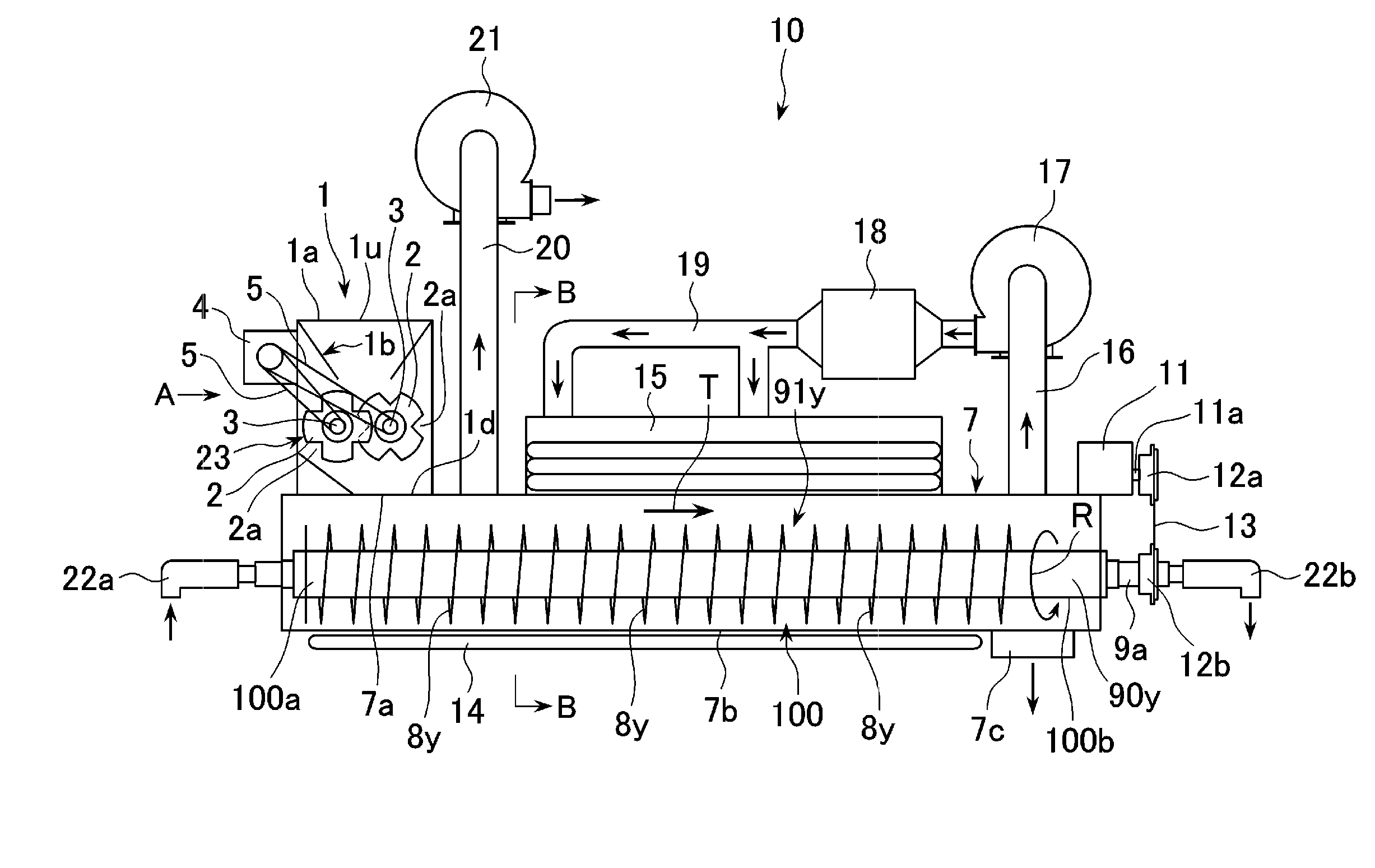
[0039]The screw conveyor 100 in accordance with the first embodiment of the present invention defines a part of a dryer 10.
[0040]As illustrated in FIG. 1, the dryer 10 includes a container 7 in which the screw conveyor 100 is housed, a motor 11 for rotating two hollow shafts 90x and 90y (having centers 90xc and 90yc, respectively) both defining a part of the screw conveyor 100, and rotary joints 22a and 22b rotatably supported the hollow shafts 90x and 90y at opposite ends thereof for allowing pre-heated moisture as heat carrier to flow in the hollow shafts 90x and 90y. A chain 13 is tensioned between a sprocket wheel 12a fixed to a drive shaft 11a of the motor 11, and sprocket wheels 12b fixed to ends 9a of the hollow shafts 90x and 90y.
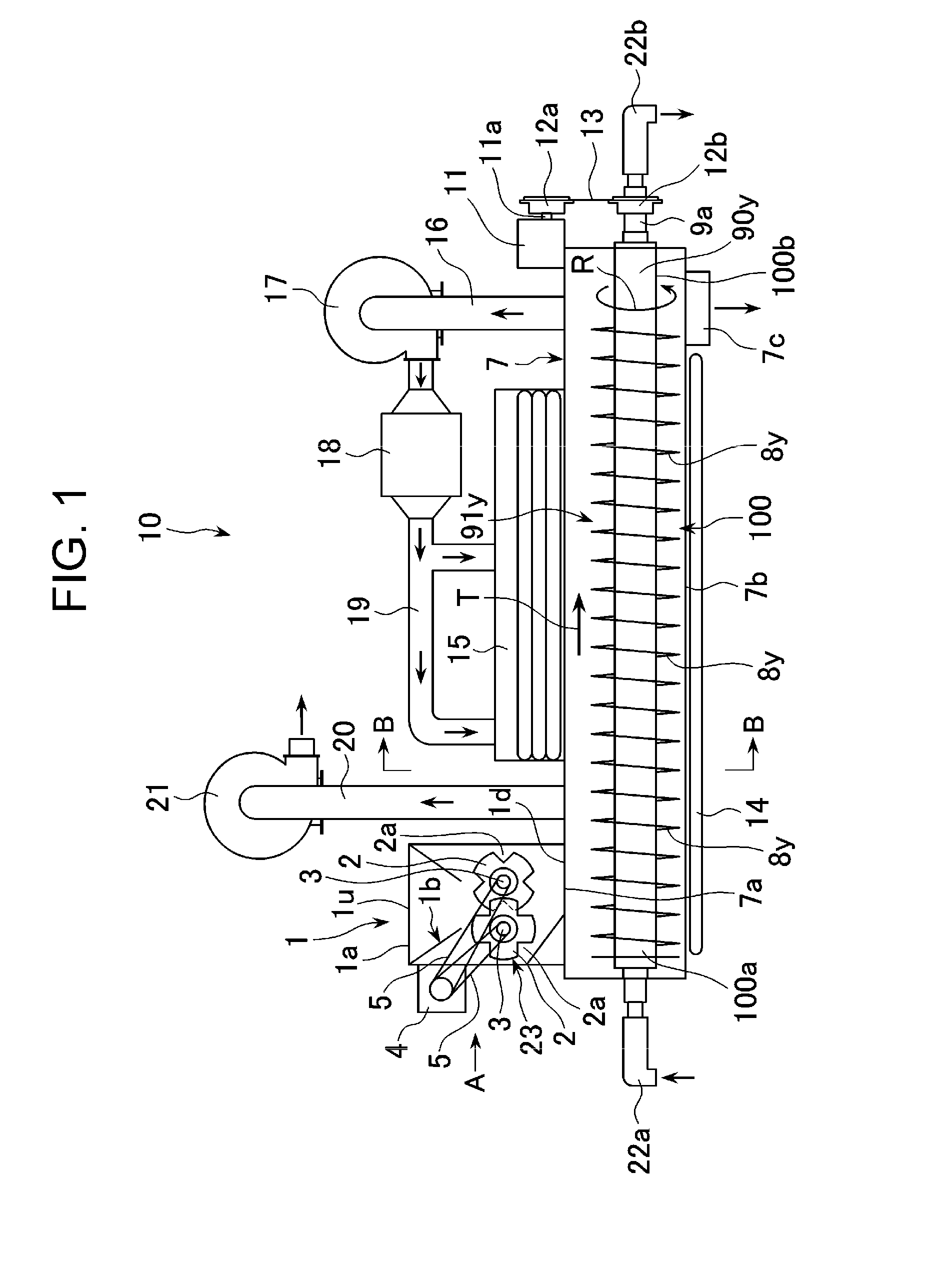
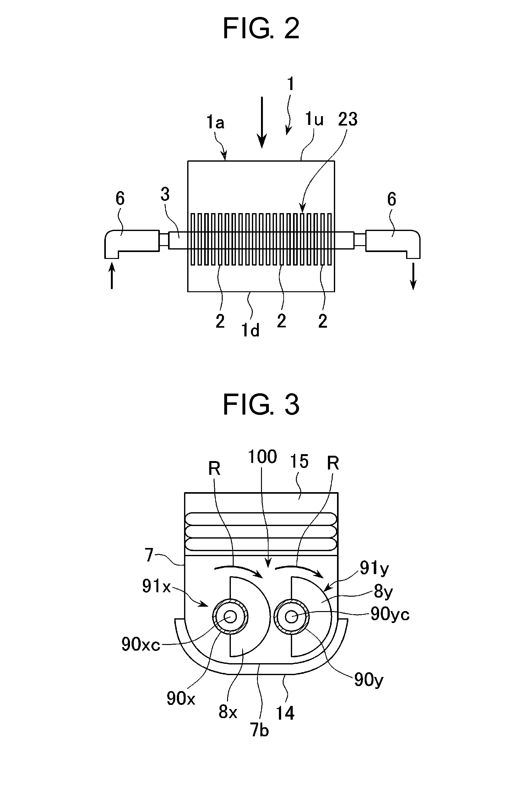
[0041]As illustrated in FIGS. 3 and 4, the screw conveyor 100 includes two rotational feeders 91x and 91y arranged in parallel with each other in the container 7. The rotational feeders 91x and 91y include, respectively, the hollow shafts 90x and 9...
second embodiment
[0067]FIG. 6 is a plane view of the feeders to be used in the screw conveyor in accordance with the second embodiment.
[0068]Whereas the rotating feeders 91x and 91y in the first embodiment are designed to include the semicircular blades 8x and 8y, each of the rotating feeders 91xa and 91ya in the second embodiment is designed to have two blades 8xa and 8ya, respectively, which are fan-shaped or arcuate (a circumferential angle being smaller than 180 degrees) when viewed in an axial direction (the direction T in FIGS. 1 and 4) of the hollow shafts 90x and 90y, as illustrated in FIG. 6.
[0069]Each of the two fan-shaped blades 8xa and 8ya has a 45-degree circumferential angle around the centers 90xc and 90yc of the hollow shafts 90x and 90y. That is, the two fan-shaped blades 8xa and 8ya are identical in shaped with each other.
[0070]Furthermore, the two fan-shaped blades 8xa and 8ya are located within a semicircular area around the centers 90xc and 90yc of the hollow shafts 90x and 90y....
third embodiment
[0077]FIG. 8 is a partial block diagram of the screw conveyor in accordance with the third embodiment.
[0078]In comparison with the screw conveyor in accordance with the first embodiment, the screw conveyor in accordance with the third embodiment additionally includes a controller 210 for controlling rotation speed of the hollow shafts 90x and 90y.
[0079]The controller 210 controls rotation speed of the hollow shafts 90x and 90y in dependence on physical properties of sludge to be fed by the screw conveyor.
[0080]Specifically, physical properties 220 of sludge to be fed by the screw conveyor, such as water content and viscosity, is input in advance to the controller 210. The controller 210 computes optimal rotation speed of the hollow shafts 90x and 90y in dependence on the received physical properties 220, and transmits a signal 230 indicative of the computed rotation speed to the motor 11. The motor 11 rotates the hollow shafts 90x and 90y at the rotation speed indicated in the rece...
PUM
 Abstract
Description
Claims
Application Information
 - R&D Engineer
- R&D Manager
- IP Professional
- Industry Leading Data Capabilities
- Powerful AI technology
- Patent DNA Extraction
Browse by: Latest US Patents, China's latest patents, Technical Efficacy Thesaurus, Application Domain, Technology Topic.
© 2024 PatSnap. All rights reserved.Legal|Privacy policy|Modern Slavery Act Transparency Statement|Sitemap